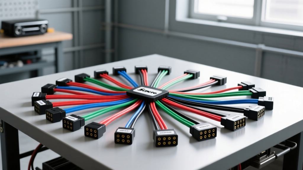
Introduction to Scosche Harness Adapters
Upgrading your factory head unit to an aftermarket stereo requires bridging the gap between your vehicle's proprietary OEM wiring and the standardized aftermarket radio harness. Scosche Industries manufactures some of the most reliable plug-and-play wiring harness adapters on the market, eliminating the need to cut or splice your vehicle's factory wiring. However, successfully completing the installation relies entirely on your ability to accurately interpret a Scosche wiring harness diagram. These diagrams map the standardized Electronic Industries Alliance (EIA) color codes of your new stereo to the specific, often highly variable, OEM wire colors of your vehicle. Misinterpreting these diagrams can lead to blown fuses, damaged CAN bus networks, or a stereo that loses its memory every time the ignition is turned off. This comprehensive guide will teach you how to decode these diagrams, understand the underlying wire specifications, and execute a professional-grade installation.
Decoding the Scosche Wiring Harness Diagram
Every Scosche harness adapter, whether it is the popular GM02B for General Motors or the FD03B for Ford vehicles, comes with a printed schematic. The diagram is typically divided into two distinct sections: the vehicle-side connector pinout and the flying-lead color map. The vehicle side illustrates the physical connector (such as a Delphi Packard 24-pin or TE Connectivity AMP plug) and identifies the cavity numbers (e.g., Pin A1, Pin B4). The flying-lead side displays the exposed wires that you must connect to your aftermarket radio's harness.
The CTA-2002 Standard vs. OEM Pinouts
To read the diagram effectively, you must understand the CTA-2002 Mobile Head Unit Wiring Standard (formerly CEA-2002). This standard dictates the color codes for the aftermarket stereo side of the equation. The Scosche wiring harness diagram acts as the translator between this universal standard and your vehicle's unique electrical architecture. Below is a reference table demonstrating how a standard Scosche GM harness (GM02B) translates CTA-2002 colors to OEM GM wire colors.
| Function | CTA-2002 Color (Radio Side) | Scosche OEM Color (Vehicle Side) | Typical AWG |
|---|---|---|---|
| +12V Constant (Memory) | Yellow | Orange | 18 AWG |
| +12V Accessory (Ignition) | Red | Yellow | 18 AWG |
| Chassis Ground | Black | Black / White Stripe | 18 AWG |
| Power Antenna / Amp Turn-On | Blue / White Stripe | Brown | 20 AWG |
| Illumination / Dimmer | Orange / White Stripe | Gray | 22 AWG |
| Left Front Speaker (+) | White | Tan | 20 AWG |
| Left Front Speaker (-) | White / Black Stripe | Gray | 20 AWG |
Wire Specifications and AWG Ratings
When matching wires based on the Scosche wiring harness diagram, you must also consider the American Wire Gauge (AWG) and the conductor material. According to SAE J1128 standards for low-tension primary cables, automotive wiring must withstand high temperatures, vibration, and chemical exposure. Scosche typically uses bare copper or tinned copper stranded wire with PVC or cross-linked polyethylene (XLPE) insulation.
- Power and Ground (18 AWG): The Yellow, Red, and Black wires are typically 18 AWG, capable of handling up to 16 amps continuously. This is sufficient for the standard 10-amp fuse protecting most aftermarket head units.
- Speaker Outputs (20 AWG): Speaker wires are generally 20 AWG. While thicker wire is technically better for long runs, 20 AWG is perfectly adequate for the short runs inside a dashboard cavity and matches the output terminals on most head units.
- Data and Accessory (22 AWG): Wires for illumination, power antenna, and steering wheel control interfaces are usually 22 AWG, as they carry minimal current (often under 1 amp) or serve as high-impedance signal references.
Step-by-Step Installation Guide
Once you have cross-referenced the Scosche wiring harness diagram with your aftermarket stereo's manual, you are ready to make the physical connections. Never attempt to wire the harness while it is plugged into the vehicle or while the car battery is connected.
Step 1: Wire Preparation and Stripping
Cut both the Scosche harness leads and the aftermarket radio leads to a uniform length, leaving enough slack to work comfortably outside the dashboard. Use a precision wire stripper calibrated for the specific AWG of the wire. For 18 AWG wire, strip exactly 5/16-inch (8mm) of insulation. Stripping too much leaves exposed copper prone to short circuits; stripping too little results in a weak mechanical crimp that will fail under the vibration of the vehicle chassis.
Step 2: Making the Connection (Crimp vs. Solder)
While twisting wires and using electrical tape is a common amateur mistake, it leads to oxidation and increased electrical resistance over time. You have two professional options:
- Adhesive-Lined Heat Shrink Butt Crimps: Insert the stripped ends of the matching wires into opposite sides of a nylon-insulated butt connector (rated for 22-18 AWG). Use a ratcheting crimp tool to apply uniform pressure. Once crimped, apply heat using a heat gun until the adhesive melts and seals the connection, providing a waterproof, vibration-proof bond.
- Rosin-Core Soldering: Twist the stripped strands together, apply 60/40 rosin-core solder, and slide a piece of 3:1 shrink-ratio tubing over the joint. Never use acid-core plumbing solder, as it will corrode the copper strands and cause an open circuit.
Step 3: Managing the Data Bus and CAN Wires
Modern Scosche diagrams often include wires for Class 2 Serial Data, GMLAN, or CAN bus networks (typically represented by Violet, Violet/White, or Pink wires). Do not connect these directly to your aftermarket radio. These are high-speed data lines used by the vehicle's Body Control Module (BCM). If your Scosche diagram includes these, you must route them to a dedicated data interface module (such as an Axxess ASWC-1 or Scosche XSVR-01) to retain steering wheel controls and chimes. Connecting a CAN bus wire directly to a 12V accessory lead will instantly destroy the vehicle's communication network.
Common Diagram Misinterpretations and Troubleshooting
Even with a clear Scosche wiring harness diagram, installation errors occur. Use this decision tree to diagnose common electrical faults:
- Symptom: Radio loses presets and clock every time the car is turned off.
Cause: The CTA-2002 Yellow (Constant 12V) and Red (Accessory 12V) wires are swapped.
Fix: Re-examine the Scosche diagram. In many GM and Chrysler vehicles, the OEM Yellow wire is actually the Accessory feed, while the OEM Orange wire is the Constant feed. Swap the connections at the butt splices. - Symptom: Alternator whine or high-pitched engine noise through the speakers.
Cause: Ground loop caused by improper grounding.
Fix: Ensure the Black ground wire from the Scosche harness is connected exclusively to the Black ground wire of the aftermarket radio. Do not ground the radio's black wire to the vehicle's metal chassis; rely entirely on the OEM ground pin mapped in the Scosche diagram to ensure a common ground reference with the vehicle's amplifier and audio system. - Symptom: Blown 10A or 15A fuse immediately upon inserting the key.
Cause: Power wire shorted to ground or miswired illumination wire.
Fix: Check the diagram's illumination wire (often Orange/White on the radio side). If you accidentally connect a 12V constant source to the radio's illumination dimmer circuit, it will backfeed and blow the internal head unit fuse. Verify all low-current 22 AWG wires with a digital multimeter before applying power.
Final Verification and Testing
Before reassembling the dashboard trim, wrap the completed wire bundle in Tesa tape (fleece automotive harness tape) to eliminate rattles and provide abrasion resistance against the metal dashboard frame. Plug the Scosche adapter into the vehicle's OEM connector until you hear the terminal lock click. Reconnect the vehicle battery, turn the ignition to the 'ON' position, and verify that the head unit powers on, retains memory, and produces audio from all four channels. For further technical assistance and vehicle-specific pinout verification, always consult Scosche Official Technical Support or your vehicle's factory service manual. By strictly adhering to the Scosche wiring harness diagram and utilizing proper crimping techniques, you ensure a reliable, noise-free audio upgrade that will last the lifetime of the vehicle.