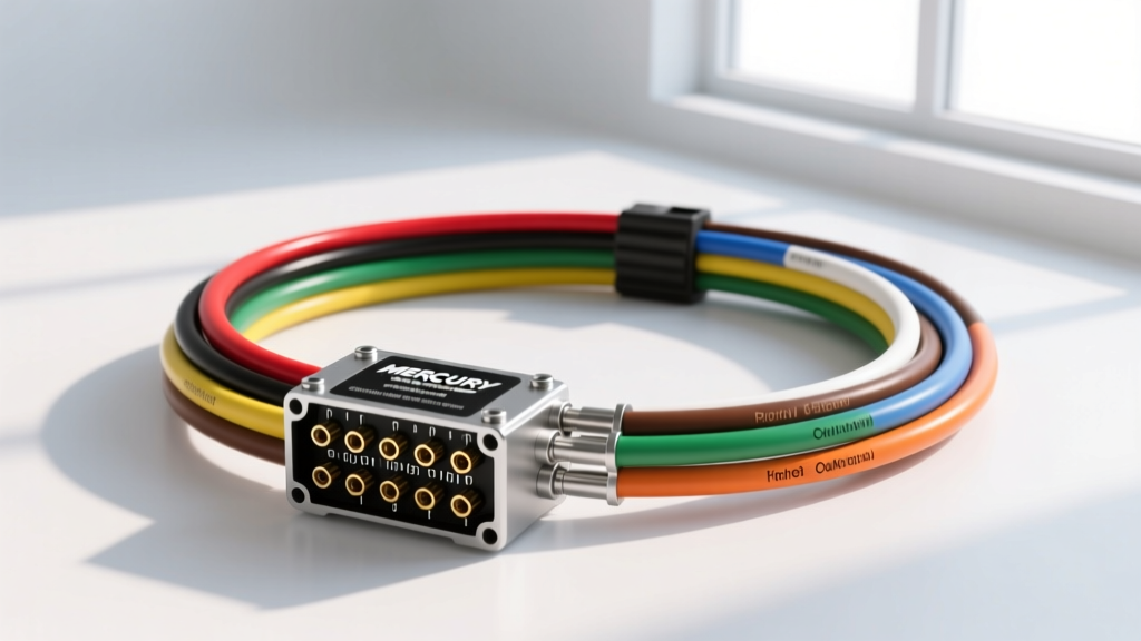
Introduction to Marine Repower Harness Upgrades
When undertaking a boat repower project, swapping an older mechanical linkage system for modern remote controls, or building a custom center console rigging harness, the electrical connection between the helm and the transom is the most critical point of failure. Locating a reliable mercury control box mercury outboard 8 pin wiring harness diagram is the first step in any successful marine electrical modification. Unlike automotive applications, marine environments subject wiring harnesses to constant vibration, high humidity, and corrosive saltwater aerosols. This guide provides a comprehensive breakdown of the standard Mercury/Mariner 8-pin rectangular connector, detailing exact pinouts, AWG requirements, and fabrication techniques for custom control box extensions.
Anatomy of the Mercury 8-Pin Rectangular Connector
The industry-standard 8-pin rectangular connector (often utilizing TE Connectivity / AMP Commercial Mate-N-Lok or specific Mercury marine housings) serves as the primary command bridge for ignition, starting, choking, and telemetry. While newer Command Link systems utilize digital CAN-bus networks, thousands of carbureted and early EFI Mercury outboards rely on this analog 8-pin harness. During an upgrade project, fabricating a custom extension or adapting an older 14-pin round plug to this 8-pin rectangular format requires strict adherence to marine-grade wire color codes and gauge specifications.
Pinout Configuration and Wire Color Codes
Below is the definitive pinout chart for the standard Mercury 8-pin control harness. Wire colors are standardized across most Mercury, Mariner, and Force outboards manufactured from the late 1980s through the EFI era.
| Pin | Wire Color | Function | Min. AWG (15ft Run) | Circuit Type |
|---|---|---|---|---|
| A (1) | Red | Battery B+ (Constant 12V) | 12 AWG | High Current |
| B (2) | Yellow | Start Solenoid | 12 AWG | High Current |
| C (3) | Dark Blue | Choke / Primer | 16 AWG | Low Current |
| D (4) | Black | Ground / Magneto Kill | 14 AWG | Ground |
| E (5) | Gray | Tachometer Signal | 18 AWG | Signal / Telemetry |
| F (6) | Purple | Ignition Switch B+ (Switched) | 14 AWG | Low Current |
| G (7) | Tan | Overheat / Temp Alarm | 18 AWG | Signal / Telemetry |
| H (8) | White / Pink | Fuel Restriction / Spare Alarm | 18 AWG | Signal / Telemetry |
Custom Fabrication: Building an 8-Pin Extension Harness
Many boat builders and repower specialists find that the factory-supplied engine harness is too short to reach the helm, especially on large center consoles or dual-console layouts. Building a custom extension harness requires specific materials to comply with the American Boat & Yacht Council (ABYC) E-11 standards for marine DC electrical systems.
Material Selection and ABYC Compliance
Never use standard automotive copper wire for a marine outboard harness. You must use UL 1426 certified marine-grade wire (e.g., Ancor or Genuinedeck). This wire features tinned, stranded copper to resist galvanic corrosion and black soot formation inside the insulation jacket. Furthermore, the insulation is rated for 105°C in dry environments and 75°C in wet bilge environments. According to ABYC E-11, the Red (Battery B+) wire must be protected by an inline fuse or circuit breaker located within 7 inches of the battery connection point to prevent catastrophic fires in the event of a short circuit.
Terminal Crimping and Weather Sealing
The 8-pin rectangular housing requires specific open-barrel or closed-barrel terminals depending on the exact AMP housing generation you are using. For a waterproof modification project: 1. Strip exactly 5/32" of insulation from the tinned marine wire. 2. Use a ratcheting marine crimper (such as the IWISS SN-28B or equivalent) to ensure a gas-tight crimp. A gas-tight crimp prevents oxygen and moisture from wicking up the wire strands via capillary action. 3. Slide heat-shrink tubing with marine-grade adhesive lining over the terminal barrel before crimping, and apply heat until the adhesive seals the wire jacket. 4. Apply a small amount of Nyogel 760G dielectric grease to the connector pins before mating the male and female housings to prevent saltwater intrusion.
Adapting Legacy Control Boxes to Modern Outboards
A common upgrade scenario involves retaining a vintage boat's original steering and throttle control box while installing a newer Mercury outboard. Older OMC or early Mercury systems sometimes utilized a 14-pin round Amphenol-style connector or a 6-pin setup. To adapt these to the modern 8-pin rectangular format, you must map the functions correctly. The most frequent pitfall is confusing the Ground/Kill circuit. On some legacy harnesses, the kill circuit relies on interrupting the ground path, whereas modern Mercury harnesses use the Black wire to ground the ignition coils directly to the engine block. Always verify the engine-side pigtail using a multimeter before applying 12V power to the Red or Purple wires.
Troubleshooting Common Harness Faults
Even with a perfect wiring diagram, real-world modification projects encounter faults. Use this diagnostic matrix to troubleshoot common issues related to the 8-pin control harness.
| Symptom | Probable Cause | Diagnostic Step | Solution |
|---|---|---|---|
| Starter clicks, but engine won't crank | Voltage drop on Yellow (Start) wire due to undersized gauge or corrosion. | Measure voltage at the engine solenoid trigger terminal while holding the key in the START position. | Upgrade the Yellow wire to 10 AWG or 12 AWG for runs exceeding 15 feet. Clean all inline bullet connectors. |
| Tachometer reads erratic or bounces at idle | EMI interference on Gray (Tach) signal wire or poor ground. | Inspect harness routing. Verify the Black ground pin has continuity to the engine block. | Reroute the Gray wire away from high-tension ignition leads and the alternator stator. Do not bundle signal wires with high-current B+ wires. |
| Engine will not shut off when key is turned to OFF | Chafed Purple (Ignition) wire shorting to a 12V source, or broken Black (Kill) wire. | Disconnect the 8-pin plug at the engine. If the engine dies, the fault is in the helm harness. If it stays running, the fault is in the engine harness or key switch. | Inspect the helm harness for sharp bulkhead edges. Repair using adhesive-lined heat shrink and apply split-loom conduit. |
| Overheat alarm sounds randomly at cruise | Galvanic corrosion on Pin G (Tan) causing a false ground trigger. | Disconnect the Tan wire at the engine temp sensor. If the alarm stops, the sensor or wire is at fault. | Clean the 8-pin connector housing with electrical contact cleaner. Apply dielectric grease to Pin G and replace the temp sensor if resistance is out of spec. |
Final Torque and Routing Specifications
When terminating the Red (B+) and Black (Ground) wires at the engine block or starter solenoid, proper torque is vital. Marine vibration will loosen improperly torqued ring terminals, leading to arcing and melted insulation. For standard 5/16" stainless steel or brass studs on Mercury outboards, torque the terminal nuts to 96-120 in-lbs (8-10 ft-lbs). Always use a star washer or lock washer between the nut and the terminal to maintain clamping force. Finally, secure the harness every 12 to 18 inches using UV-resistant nylon cable ties or stainless steel P-clamps, ensuring the harness has a drip loop before entering the engine cowl to prevent water from tracking directly into the 8-pin connector housing.
Authoritative References
- American Boat & Yacht Council (ABYC) - E-11 Standard for AC & DC Electrical Systems on Boats.
- Mercury Marine - Outboard Installation and Rigging Manuals (Section: Electrical and Ignition).
- TE Connectivity - Commercial Mate-N-Lok and Marine Rectangular Connector Specifications.