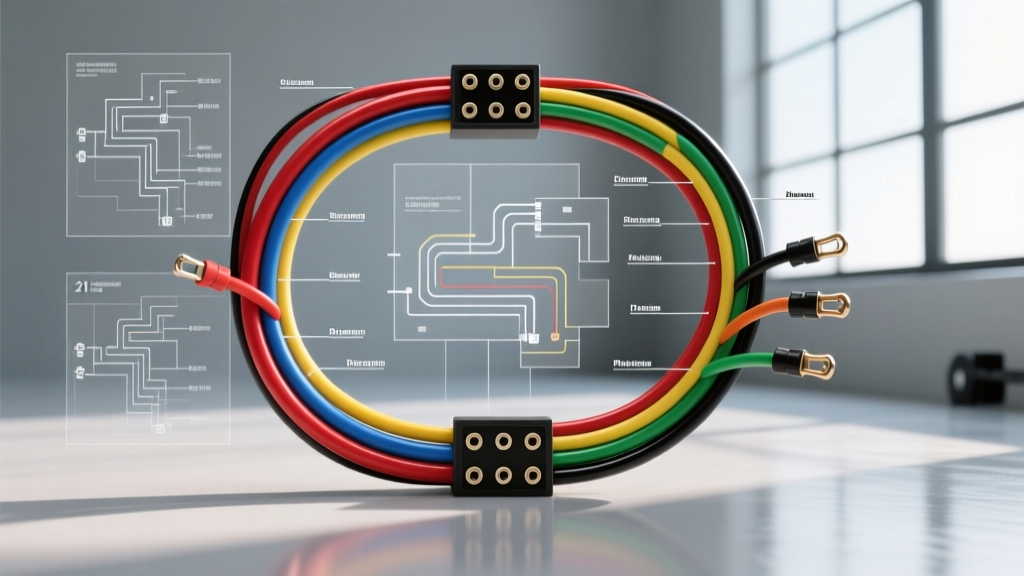
Understanding the 21 Circuit Wiring Harness
When building a traditional hot rod, classic truck, or street rod, the electrical system often induces the most anxiety for beginners. The 21 circuit wiring harness represents the absolute sweet spot for vintage builds. Unlike modern vehicles that require 28 to 40+ circuits to manage complex CAN-bus networks, ABS modules, and power accessories, a classic build requires a streamlined, robust, and easy-to-troubleshoot system. A standard 21 circuit wiring harness provides dedicated, fused pathways for every essential OEM-style component—from ignition and lighting to wipers and the horn—without the overwhelming bloat of unused wires.
For a beginner, this kit size offers the perfect balance of comprehensive coverage and manageable complexity. By understanding the fundamental layout, wire gauge requirements, and routing strategies outlined in this guide, you can confidently wire your chassis from the firewall forward and backward.
The Anatomy of a 21-Circuit Kit
Before cutting a single zip tie, you must understand what is inside the box. A high-quality 21 circuit chassis harness utilizes cross-linked polyethylene (XLPE) insulated wire, meeting SAE J1128 standards for TXL or GXL wire. This thin-wall insulation allows for tighter bundling and higher heat resistance compared to older PVC wires.
The core of the system is the fuse block, typically housing 21 standard ATO/ATC blade fuses. The harness is usually divided into three main sub-assemblies: the main cabin harness, the front lighting/engine sub-harness, and the rear lighting sub-harness. These are pre-terminated at the fuse block and left unterminated at the device ends, allowing you to custom-fit the lengths to your specific chassis dimensions.
The 21-Circuit Breakdown: Specifications and Color Codes
While specific color codes can vary slightly between manufacturers like Painless Performance or American Autowire, the industry relies on a generally accepted color palette for automotive 12V DC systems. Below is the standard circuit mapping, wire gauge (AWG), and fuse rating for a typical 21 circuit wiring harness.
| # | Circuit Function | Wire Color (Typical) | AWG Size | Fuse Rating |
|---|---|---|---|---|
| 1 | Headlights (High Beam) | Yellow | 12 AWG | 15A |
| 2 | Headlights (Low Beam) | Green | 12 AWG | 15A |
| 3 | Taillights / Parking | Brown | 14 AWG | 10A |
| 4 | Dash / Instrument Lights | Gray | 18 AWG | 5A |
| 5 | Stop/Turn Left | Dark Green | 14 AWG | 15A |
| 6 | Stop/Turn Right | Dark Blue | 14 AWG | 15A |
| 7 | Horn (Relay Trigger) | Purple | 14 AWG | 15A |
| 8 | Wipers | White | 14 AWG | 15A |
| 9 | Radio / Stereo Memory | Orange | 14 AWG | 10A |
| 10 | Cigar Lighter / 12V Aux | Light Blue | 14 AWG | 15A |
| 11 | Gauge Cluster Power | Pink w/ Black Stripe | 18 AWG | 5A |
| 12 | Ignition (Run/Start) | Pink | 10 AWG | 20A |
| 13 | Start Signal (Solenoid) | Purple | 10 AWG | 20A |
| 14 | Blower Motor (HVAC) | Light Green | 14 AWG | 15A |
| 15 | Backup Lights | Light Green w/ White | 14 AWG | 10A |
| 16 | Electric Cooling Fan | Red | 12 AWG | 20A |
| 17 | Electric Fuel Pump | Tan | 14 AWG | 15A |
| 18 | Coil / HEI Ignition | Pink w/ White Stripe | 12 AWG | 15A |
| 19 | Dome / Interior Light | White w/ Red Stripe | 16 AWG | 10A |
| 20 | Aux 1 (Power Windows) | Red w/ White | 12 AWG | 20A |
| 21 | Aux 2 (General Accessory) | Red w/ Black | 14 AWG | 15A |
Relay Fundamentals: Protecting Your Switches
A common beginner mistake is routing full headlight or horn current directly through the dashboard switches. The 21 circuit wiring harness is designed to use switches as low-amperage triggers for high-amperage relays. For example, Circuit #1 and #2 (Headlights) should route to the coil terminals (85/86) of a standard ISO mini relay. The heavy 10 AWG power feed from the battery connects to the relay's power terminal (30), and the output (87) sends direct, unfused power to the headlights (which are protected by a maxi-fuse at the battery source). This prevents voltage drop across the dash and ensures your vintage headlight switches do not melt under heavy amperage loads.
Routing and Firewall Penetration
Routing the front sub-harness through the firewall requires careful planning. Never drill a bare metal hole and pass wires through it; engine vibration will slice through the insulation and cause a dead short to the chassis. Always use a rubber firewall grommet. For a 21-circuit kit, a 2.5-inch to 3-inch diameter grommet is usually required. Apply a silicone-based dielectric grease to the wires and the inside of the grommet to reduce friction during installation.
Under the hood, maintain a minimum clearance of 6 inches between the wiring loom and exhaust headers. If you must cross an exhaust component, use high-temperature Teflon sleeving or fiberglass heat shield tubing over the harness. Secure the harness every 8 to 12 inches using UV-resistant nylon zip ties or Adel clamps (cushioned metal clamps) to prevent the wires from chafing against sharp chassis edges.
Termination and Crimping Standards
The reliability of your 21 circuit wiring harness depends entirely on the quality of your terminations. According to IPC/WHMA-A-620 harness assembly standards, a proper crimp must achieve a gas-tight mechanical bond where the wire strands and terminal deform together without cutting or slicing the copper.
- Tooling: Avoid cheap, non-ratcheting crimpers. Invest in a ratcheting crimper specifically calibrated for the terminal type you are using (e.g., Delphi Weather-Pack, Molex MLX, or standard ring terminals).
- Heat Shrink: Always use adhesive-lined (dual-wall) heat shrink. When heated, the inner lining melts and seals the back of the terminal, preventing moisture from wicking up into the copper strands via capillary action—a primary cause of green corrosion and high resistance.
- Soldering: Do not solder crimp terminals in automotive applications. Solder is brittle and will crack under the constant vibration of a vehicle chassis, leading to intermittent open circuits.
Grounding: The Silent Killer of Electrical Systems
A 21 circuit wiring harness relies heavily on the vehicle's steel chassis to complete the circuit back to the battery's negative terminal. If your grounds are poor, your headlights will dim, your gauges will read erratically, and your fuel pump will starve for voltage. Establish a strict grounding hierarchy:
- Master Ground: Run a 1/0 AWG (or minimum 2 AWG) flexible copper cable from the battery negative terminal directly to the engine block.
- Engine to Chassis: Use a 4 AWG braided copper ground strap from the engine block or cylinder head to the firewall or chassis rail to ensure the engine is bonded to the body.
- Body to Chassis: If you are working on a truck with a separate cab and bed, or a fiberglass-bodied hot rod, you must run 8 AWG ground straps from the bed/doors to the main chassis.
- Component Grounds: Sand away all paint, powder coat, and rust at every grounding point. Use star washers to bite into bare metal, and coat the completed connection with dielectric grease to prevent oxidation.
Final Pre-Power Checklist
Before connecting the battery, consult resources like the Mad Electrical Technical Guides to verify your alternator excitation wire and ignition switch pinouts. Pull all fuses from the 21-circuit fuse block. Connect the battery and use a multimeter to verify that you have 12.6V at the main power feed stud. Insert fuses one by one, testing each circuit individually. This methodical approach ensures that if a short exists in the taillight wiring, you will not accidentally fry your new ignition coil or radio. By respecting wire gauges, utilizing proper relays, and executing gas-tight crimps, your 21 circuit wiring harness will provide decades of reliable, spark-free service.