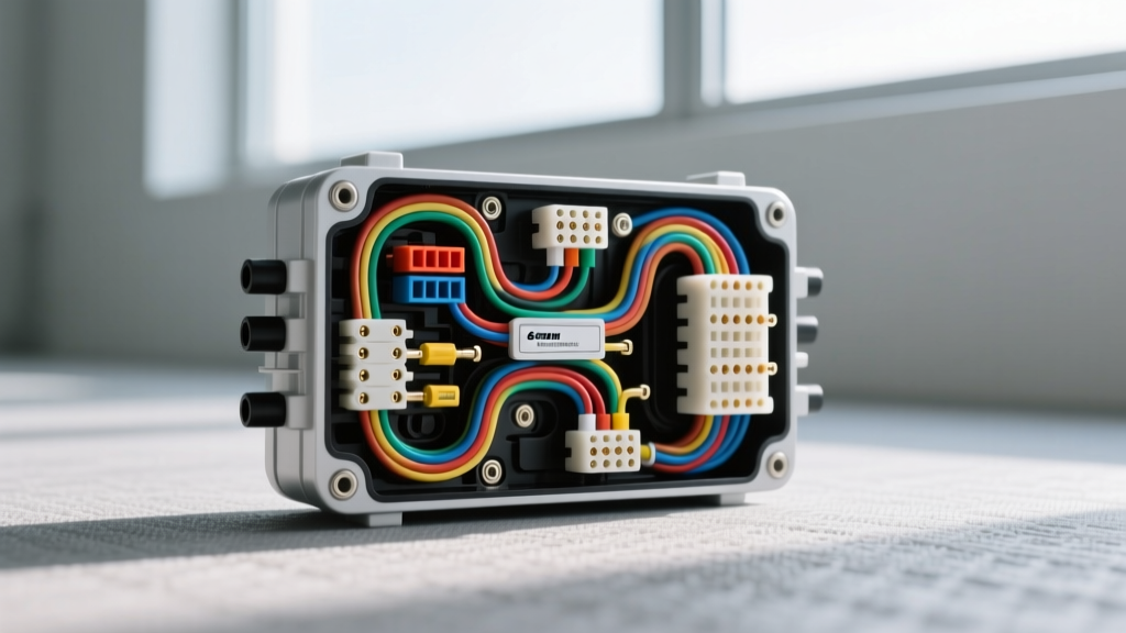
Introduction to 6.7L ISB Harness Vulnerabilities
The 6.7L Cummins ISB engine, found in 2007.5 through current Ram 2500 and 3500 HD trucks, operates in an environment defined by extreme vibration, intense heat, and high electrical loads. When diagnosing drivability issues, performing an engine swap, or installing an aftermarket 6.7 Cummins wiring harness, technicians and DIYers frequently make critical errors. These mistakes range from improper grounding to routing harnesses too close to the exhaust gas recirculation (EGR) cooler. Because modern Ram HD trucks rely heavily on the Controller Area Network (CAN) bus and sensitive 5-volt reference circuits, a single chafed wire can cascade into a total ECM failure. This guide details the most common mistakes, severe safety warnings, and expert-level corrections for the 6.7 Cummins wiring harness.
Mistake #1: Ignoring the EGR Cooler and Valve Cover Chafe Points
The most notorious failure point on the 6.7 Cummins wiring harness is the main engine harness routing near the valve cover and the EGR cooler heat shield. Over tens of thousands of miles, engine vibration causes the harness to rub against the sharp aluminum edge of the valve cover or the metal heat shielding.
The Failure Mode
When the outer loom wears through, the individual wires begin to chafe. The most commonly affected circuits are the injector solenoid/piezo control wires and the CAN-C bus lines. If the CAN-C High (typically Violet/White) and CAN-C Low (White/Violet) wires short together or to ground, the ECM loses communication with the Transmission Control Module (TCM) and the instrument cluster, resulting in a 'No Start' condition and a U0100 diagnostic trouble code.
The Expert Fix
- Inspection: Always pull back the split loom and inspect the harness where it passes the rear of the valve cover and the EGR cooler bracket.
- Protection: Never use standard corrugated plastic loom in high-heat zones. Wrap the repaired harness in SAE J1128 compliant high-temperature fiberglass sleeving or use OEM-style Tesa tape (PVC fleece harness tape) followed by a high-temp nylon braided sleeve.
- Rerouting: Use UV-resistant zip ties to secure the harness away from the heat shield, ensuring a minimum 1-inch clearance from any sharp metal edges.
Mistake #2: Incorrect Grounding and Voltage Drop Blindness
The 6.7L Cummins requires massive amperage to crank the high-compression diesel block, especially in cold weather. A common mistake during harness installation or engine swaps is relying on painted surfaces for grounds or using undersized ground cables.
Grounding Specifications & Torque
The main engine block ground (G104) and the ECM ground circuits are critical. The ECM uses dedicated ground pins on the 120-pin connector to read sensor returns. If the main block ground has high resistance, the sensor return voltage will float, causing the ECM to read phantom codes for the MAP, EBP, and APPS sensors.
| Ground Point | Location | Wire/Cable Size | Torque Spec | Preparation |
|---|---|---|---|---|
| G104 (Main Block) | Passenger side engine block | 2 AWG (Battery to Block) | 35 Nm (26 ft-lbs) | Sand to bare metal, apply dielectric grease |
| G105 (ECM Ground) | Driver side cylinder head | 10 AWG (Black) | 12 Nm (9 ft-lbs) | Clean mounting surface, check for corrosion |
| G110 (Chassis) | Driver side frame rail | 4 AWG (Block to Frame) | 45 Nm (33 ft-lbs) | Remove paint/powder coat completely |
Note: Always perform a voltage drop test across the ground cable while cranking. A reading above 0.1V indicates excessive resistance requiring immediate cable or terminal replacement.
Mistake #3: Splicing High-Amp Circuits with Improper Connectors
When repairing a damaged 6.7 Cummins wiring harness, many technicians use standard butt splices or twist-and-tape methods on high-current circuits like the glow plug relay feeds or the fuel heater circuit. These circuits routinely see 40 to 80 amps of continuous draw during cold starts.
The Right Way to Splice
According to Mopar Wiring Repair Standards, any splice on a circuit carrying more than 20 amps must utilize a heavy-duty, adhesive-lined heat shrink crimp terminal, or preferably, the wire should be replaced back to the nearest OEM connector. For sensor and low-amperage circuits, use OEM-style splice bands (brass crimp sleeves) sealed with dual-wall heat shrink. Never use electrical tape as a primary moisture seal under the hood of a Ram HD; it will unravel when exposed to the 120°F+ ambient under-hood temperatures generated by the 6.7L turbocharger.
CRITICAL SAFETY WARNING: The 5-Volt Reference Short
WARNING: Before unplugging, probing, or repairing any part of the 6.7 Cummins wiring harness, you MUST disconnect BOTH negative battery cables. The Ram HD utilizes dual batteries, and leaving even one connected keeps the ECM energized.
The ECM supplies a highly regulated 5-volt reference signal to critical sensors (APPs, MAP, EBP, Fuel Rail Pressure). This circuit is typically a Pink/White (PK/WT) or Violet/White (VT/WT) wire. If you accidentally short this 5V reference wire to a 12-volt battery feed while probing with a multimeter or test light, you will instantly destroy the internal voltage regulator inside the ECM. This is a catastrophic, non-warranty failure that requires a $1,500+ ECM replacement and a trip to the dealer for programming. Always use a high-impedance digital multimeter (DMM) and verify the circuit is dead before piercing wire insulation.
Mistake #4: Aftermarket Sensor Harness Routing
Owners installing aftermarket lift pumps, turbo chargers, or tuning modules often route their supplemental wiring harnesses too close to the factory 6.7 Cummins wiring harness. If an aftermarket high-amperage wire (like a 10 AWG feed for an AirDog or FASS fuel system) is bundled tightly with the factory CAN bus lines, electromagnetic interference (EMI) can corrupt the data packets. This results in erratic tachometer readings, harsh transmission shifts, or random ECM resets. Always cross high-amperage aftermarket wires at a 90-degree angle to the factory harness, never run them parallel for extended distances.
Diagnostic Decision Tree: 6.7L Cummins Harness Faults
Use the following troubleshooting matrix to quickly isolate harness-related faults on the 6.7L ISB engine. This data is cross-referenced with Cummins QuickServe electrical schematics for CM2250 and CM2350 ECM platforms.
| Symptom | Probable Harness Fault | Circuit / Wire Color | Expert Fix / Verification |
|---|---|---|---|
| Random Cylinder Misfire (P0201-P0206) | Injector harness chafing at valve cover edge | K12-K17 (Injector Control) | Perform a cylinder cutout test. Inspect valve cover pass-through connector for pushed-out pins or melted seals. |
| No Start, ECM Dead, No Dash Lights | 5V Reference shorted to 12V or Ground | F855 (PK/WT) 5V Ref | Disconnect ECM 120-pin. Check resistance between Pin 29 and ground. Trace to APPS/MAP sensor harness. |
| Crank/No Start, U0100 Code | CAN-C Bus open circuit or short | D55 (VT/WT) & D54 (WT/VT) | Check 120-pin ECM connector pins 19 & 20. Verify 60 ohms total network resistance with batteries disconnected. |
| Slow Crank, High Voltage Drop | Corroded G104 Engine Block Ground | 2 AWG Black Cable | Clean block pad to bare metal. Apply anti-corrosion compound and torque M10 bolt to 35 Nm. |
| Fuel Heater Inoperative (P0253) | Chafed fuel heater feed near filter housing | C15 (RD/DG) 12V Feed | Inspect harness where it drapes over the fuel filter bracket. Repair with adhesive heat shrink and secure with tie-wrap. |
Best Practices for Harness Maintenance and Swaps
Whether you are maintaining a stock 2018 Ram 3500 or performing a 6.7 Cummins swap into a classic chassis, treat the wiring harness with the same respect as the fuel system. Use OEM Mopar Connection Systems or high-quality Deutsch DT/TE Connectivity equivalents when replacing damaged pigtails. Never leave a connector cavity empty; always use the proper silicone cavity plugs to prevent moisture ingress and terminal corrosion. By avoiding these common mistakes and adhering to strict safety protocols, you ensure the longevity and reliability of your Cummins diesel electrical system.