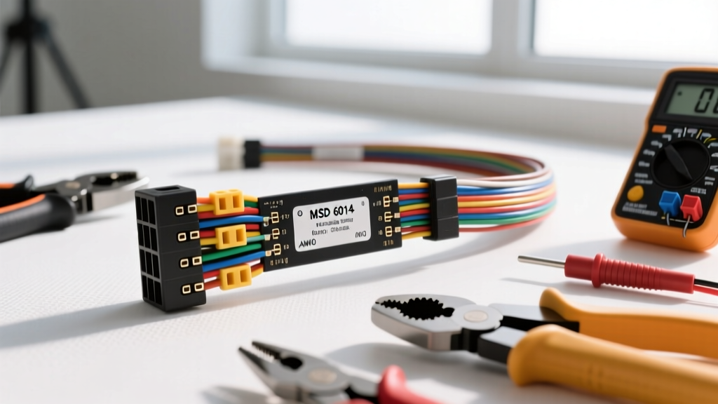
Introduction to MSD 6014 LS Swap Integration
Executing a General Motors LS engine swap requires precise management of the 24x reluctor ignition and sequential fuel injection systems. The MSD 6014 GM LS EFI Ignition Controller is a premier standalone solution for 1997-2006 LS1, LS2, and LS6 engines, eliminating the need for a bulky factory PCM and VATS bypass modules. However, the MSD 6014 wiring harness is not a universal plug-and-play kit for custom chassis applications. It requires strategic integration with the host vehicle's power distribution, fuel pump relays, and switched ignition circuits. This comprehensive analysis breaks down the true financial investment and the specialized tooling required to fabricate, modify, and validate an MSD 6014 harness installation, ensuring your high-performance swap starts on the first crank.
Comprehensive Cost Breakdown: Harness & Ancillary Components
Many enthusiasts budget solely for the MSD 6014 controller and its included harness, only to encounter hidden costs when adapting the harness to a custom firewall bulkhead or upgrading the power delivery system. Below is a realistic cost analysis for a professional-grade harness integration.
| Component Category | Specific Item / Specification | Estimated Cost (USD) |
|---|---|---|
| Core Controller & Harness | MSD 6014 GM LS EFI Ignition Controller Kit | $650.00 - $725.00 |
| Supplemental Wire | SAE J1128 GXL Cross-Linked Wire (10, 16, 18 AWG) | $45.00 - $60.00 |
| Connectors & Terminals | Weather-Pack & Metri-Pack 280 Series (Aptiv/Delphi) | $55.00 - $80.00 |
| Power Distribution | 40A MIDI Fuse, Bosch-Style 5-Pin Relays, Heavy Duty Ring Terminals | $35.00 - $50.00 |
| Environmental Protection | 3M EPS300 Adhesive-Lined Heat Shrink, Techflex Braided Sleeving | $40.00 - $65.00 |
| Total Estimated Project Material Cost | $825.00 - $980.00 | |
Note: The MSD 6014 harness includes the primary coil and injector pigtails, but extending these wires to accommodate a mid-engine or rear-mounted transaxle layout will push your supplemental GXL wire and connector costs to the higher end of the spectrum.
Essential Tooling for Harness Fabrication and Modification
Attempting to build or modify an EFI harness with generic hardware store crimpers and electrical tape is a guaranteed path to voltage drop, intermittent misfires, and catastrophic ECU failure. The MSD 6014 relies on precise square-wave signals and high-current coil charging; terminal integrity is non-negotiable.
1. Open-Barrel Crimping Tools
The automotive industry standard for EFI sensors and injectors is the open-barrel terminal (specifically the Aptiv Metri-Pack 280 and Weather-Pack series). You must use a crimping tool designed with a 'W' or 'B' die profile to fold the wire wings and insulation wings correctly.
- Recommended Tool: Delphi 12094430 or IWISS SN-28B.
- Crimp Height Specification: For 18-20 AWG wire, the conductor crimp height must be precisely 1.40mm - 1.55mm. An over-crimped terminal will shear the copper strands; an under-crimped terminal will allow moisture ingress and oxidation.
2. Wire Stripping & De-Pinning Tools
Standard rotary strippers can nick the copper strands of fine-strand automotive wire, reducing the effective AWG and creating a localized hot spot. Use precision jaw strippers calibrated for thin-wall GXL insulation. Furthermore, modifying the MSD main ECU connector requires specialized pin extraction tools to back out Metri-Pack terminals without shattering the plastic connector housing tangs.
3. Diagnostic & Validation Equipment
Before applying 12V power to the MSD 6014, you must validate your custom power and ground extensions. A high-impedance Digital Multimeter (DMM) like the Fluke 87V is required for voltage drop testing. According to EFI University Wiring Harness Fundamentals, any voltage drop greater than 0.1V across a power or ground circuit under load indicates insufficient wire gauge or a poor crimp.
MSD 6014 Main Harness Pinout and Wire Gauge Specifications
When extending the MSD 6014 main power and sensor harness, you must adhere to strict SAE wire gauge requirements to handle the inductive loads of the LS coil packs and the peak-and-hold current of the fuel injectors. The following table outlines the critical circuits exiting the main MSD power connector.
| Circuit Function | MSD Wire Color | Minimum AWG (GXL) | Termination / Routing Notes |
|---|---|---|---|
| Main Battery Power (Coils/Injectors) | Heavy Red | 10 AWG | Must route directly to battery positive via a 40A MIDI fuse. Do not share with starter solenoid. |
| Main Power Ground | Heavy Black | 10 AWG | Terminate to a clean, bare metal point on the engine block. Use a star washer to bite through paint. |
| Switched Ignition (12V+ Trigger) | Red | 16 AWG | Connect to ignition switch 'Run/Start' circuit. Use a 5A inline ATC fuse. |
| Sensor / Logic Ground | Black | 16 AWG | Must share the exact same engine block grounding point as the Heavy Black to prevent ground loops. |
| Fuel Pump Relay Trigger | Blue | 18 AWG | Provides a ground trigger to activate a standard Bosch 5-pin fuel pump relay. |
| Tachometer Output | White | 18 AWG | 12V square wave output. May require an MSD 8918 tach adapter for older analog gauges. |
For comprehensive factory wiring schematics and pinout diagrams, always cross-reference the Holley/MSD 6014 Official Installation Guide before cutting or splicing any wires.
Hidden Costs & Real-World Failure Points
The GXL vs. PVC Wire Mistake
A common cost-cutting error is using standard PVC-insulated wire (like THHN) purchased from a local hardware store. Under-hood environments routinely exceed 100°C near the exhaust manifolds. PVC insulation melts and shorts out at 90°C. You must purchase SAE J1128 certified GXL (Cross-Linked) wire, which withstands up to 125°C. As detailed in the SAE J1128 Low Tension Primary Cable Standard, GXL wire also features a thin-wall design, allowing for tighter bend radii in crowded engine bays without stressing the copper strands.
Ground Loop Noise and Sensor Interference
The MSD 6014 processes high-resolution cam and crank position sensor signals. If the sensor ground (Black) is routed to the chassis firewall while the heavy power ground (Heavy Black) is routed to the engine block, the alternating current from the alternator will induce noise into the sensor ground. This results in erratic timing curves and severe engine knock. The Fix: Spend the extra $15 on a heavy-duty brass ground bus bar mounted directly to the engine block, tying all MSD grounds, sensor shields, and cylinder head grounds to a single star-point.
Environmental Protection and Looming Strategy
The final phase of your budget must address harness longevity. Split-loom tubing is inexpensive but traps moisture and abrasives against the wire insulation. For a professional MSD 6014 installation:
- Base Layer: Wrap the harness in Tesa 51036 PET cloth friction tape. This prevents the wires from rattling and chafing against each other.
- Outer Sleeving: Slide Techflex expandable braided sleeving over the taped bundle. It provides superior abrasion resistance and allows water to drain rather than pool.
- Termination Sealing: Where the harness enters the firewall or the MSD controller housing, use 3M EPS300 adhesive-lined heat shrink. When heated, the inner thermoplastic adhesive melts and flows into the wire interstices, creating a completely waterproof, strain-relieved seal that blocks capillary action from wicking water into the ECU pins.
Conclusion: Investing in Reliability
Building and integrating an MSD 6014 wiring harness is not merely about connecting point A to point B; it is about managing high-current inductive loads and protecting micro-volt sensor signals from electromagnetic interference. By budgeting appropriately for SAE-certified GXL wire, precision open-barrel crimpers, and adhesive-lined environmental seals, you ensure that your LS swap delivers reliable, track-proven performance for years to come. Do not let a $2 hardware store crimp tool compromise a $650 standalone ignition controller.