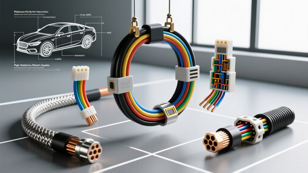
Technical Reference: Architecture of the Electric Autonomous Vehicles Wiring Harness Market
The transition from internal combustion engines to fully autonomous electric platforms has fundamentally rewritten the rules of automotive electrical architecture. As the electric autonomous vehicles wiring harness market rapidly expands, engineers and technicians are no longer dealing with simple 12V point-to-point copper networks. Modern EV and AV platforms utilize complex, dual-voltage zonal architectures that require rigorous adherence to high-voltage (HV) safety standards, high-speed data transmission protocols, and aggressive weight-reduction targets. This technical specification reference outlines the core wiring harness parameters, connector pinouts, and material standards defining today's advanced EV/AV platforms.
High-Voltage (HV) Power Distribution Specifications
Electric vehicle powertrains operate on high-voltage DC buses, typically ranging from 400V to 800V nominal (with peak transient voltages exceeding 1000V). The wiring harnesses connecting the battery management system (BMS), traction inverter, and electric drive motors must comply with strict safety and thermal standards, most notably SAE J1673 (High Voltage Automotive Harness Design) and ISO 6722-2.
Insulation and Shielding Requirements
HV cables in the electric autonomous vehicles wiring harness market universally utilize Cross-Linked Polyethylene (XLPE) or silicone rubber insulation due to their superior thermal stability (rated up to 150°C continuous) and high dielectric strength. To prevent electromagnetic interference (EMI) from disrupting sensitive AV sensor suites, HV cables employ a dual-shield design: an inner semi-conductive layer, a braided copper or aluminum-magnesium alloy shield (providing >95% optical coverage), and an outer aluminum-mylar foil wrap. Per SAE and ISO standards, the outermost jacket must be bright orange (RAL 2003) to denote high voltage.
| AWG Size | Cross-Section (mm²) | Continuous Current Rating | Outer Diameter (Nominal) | Typical Application |
|---|---|---|---|---|
| AWG 6 | 16.0 mm² | 85A - 105A | 8.2 mm | HVAC Compressor, PTC Heater |
| AWG 4 | 25.0 mm² | 125A - 150A | 10.5 mm | DC-DC Converter, OBC |
| AWG 1/0 | 50.0 mm² | 220A - 260A | 14.2 mm | Battery to Inverter (Main Bus) |
| AWG 2/0 | 70.0 mm² | 300A - 350A | 16.8 mm | Fast Charge Inlet to BMS |
Low-Voltage Data and Sensor Fusion Wiring
Autonomous driving systems (Level 3 and above) rely on sensor fusion—integrating LiDAR, radar, ultrasonic, and high-definition camera arrays. This requires massive data bandwidth, pushing the market away from legacy CAN bus networks toward Automotive Ethernet (100BASE-T1 and 1000BASE-T1). The physical layer for these networks demands highly specialized shielded twisted pair (STP) or unshielded twisted pair (UTP) cabling with strict impedance controls.
H-MTD and MATEnet Connector Pinouts
To support gigabit data transfer rates while minimizing packaging space, the industry has standardized on connectors like TE Connectivity's H-MTD (High-Speed Modular Twisted-Pair Data) and MATEnet families. These connectors feature integrated primary and secondary locking mechanisms (TPA/CPA) to prevent vibration-induced disconnects, a critical failure mode in AV applications.
| Pin Number | Signal / Function | Wire Color Code | AWG Rating | Impedance Requirement |
|---|---|---|---|---|
| Pin 1 | Data Pair A (+) | White/Blue Stripe | 24 AWG (Stranded) | 100Ω ± 5Ω |
| Pin 2 | Data Pair A (-) | Blue | 24 AWG (Stranded) | 100Ω ± 5Ω |
| Pin 3 | Data Pair B (+) | White/Orange Stripe | 24 AWG (Stranded) | 100Ω ± 5Ω |
| Pin 4 | Data Pair B (-) | Orange | 24 AWG (Stranded) | 100Ω ± 5Ω |
| Shell | EMI Ground / Shield Drain | Bare Copper Braid | N/A | < 5mΩ Termination |
When fabricating or repairing these harnesses, technicians must maintain the twist rate of the pairs (typically 15 to 25 twists per meter) right up to the crimp barrel. Untwisting more than 10mm will cause return loss and crosstalk, resulting in dropped frames from LiDAR sensors and potential autonomous navigation faults.
High Voltage Interlock Loop (HVIL) Safety Circuits
A non-negotiable safety requirement in the electric autonomous vehicles wiring harness market is the High Voltage Interlock Loop (HVIL). The HVIL is a low-voltage (typically 5V or 12V) diagnostic circuit that runs through all HV connectors and service disconnects. If an HV connector is partially unseated or a service plug is removed, the HVIL circuit breaks, prompting the BMS to immediately open the main contactors and isolate the high-voltage battery.
HVIL Pin Configuration and Diagnostics
The HVIL circuit utilizes small auxiliary pins housed within the main HV connector shell. These pins are designed to mate first and break last during connection and disconnection sequences.
- Pin Designation: Typically labeled as Pins A and B, or Pins 1 and 2 on the auxiliary cavity block.
- Wire Gauge: 18 AWG or 20 AWG, unshielded, typically colored Yellow or Green/Yellow.
- Signal Type: DC Voltage or PWM (Pulse Width Modulation) signal monitored by the Battery Energy Control Module (BECM).
- Troubleshooting: If a Diagnostic Trouble Code (DTC) such as P0AA6 (Hybrid/EV Battery Voltage System Isolation Fault) or a specific HVIL open-circuit code is set, technicians must perform a continuity check on the auxiliary pins. A common failure mode is the deformation of the female HVIL terminal due to improper insertion angle during assembly, leading to intermittent open circuits under chassis vibration.
Market Drivers: Weight Reduction and Zonal Architectures
Historically, a luxury vehicle's wiring harness could weigh upwards of 60kg and contain over 5,000 individual wires spanning 2 to 4 kilometers in length. In the electric autonomous vehicles wiring harness market, weight reduction is paramount to maximize battery range. The market is aggressively shifting toward Zonal Architectures.
Instead of running dedicated wires from every sensor and actuator back to a central gateway, zonal controllers act as local hubs. This requires the harness to transition from point-to-point copper to localized power distribution nodes and high-speed Ethernet backbones. Furthermore, to offset the heavy weight of EV battery packs, harness manufacturers are substituting copper with aluminum wiring for large-gauge HV and 12V power feeds. Aluminum requires specialized ultrasonic welding or friction-stir crimping techniques, as standard copper crimp dies will result in galvanic corrosion and high-resistance cold joints.
Galvanic Isolation and Shielding Termination
When terminating shielded data cables to AV sensor housings (which are often die-cast aluminum), the shield drain wire must be terminated using a 360-degree shield crimp ring or an internal grounding spring clip. Pigtail grounding (twisting the drain wire and routing it to a single pin) creates an antenna effect at high frequencies, rendering the EMI shield useless against the high-frequency switching noise generated by Silicon Carbide (SiC) traction inverters. Proper 360-degree shield termination ensures that high-frequency noise is safely routed to the vehicle chassis ground plane without corrupting the 1000BASE-T1 data payload.
Summary of Fabrication and Repair Standards
Working within the electric autonomous vehicles wiring harness market requires strict adherence to OEM-specific repair procedures and IPC/WHMA-A-620 standards for cable assemblies. Technicians must utilize calibrated pneumatic crimpers with force-monitoring capabilities, perform pull-force testing on HVIL terminals, and use high-voltage megohmmeters (Hi-Pot testers) to verify the dielectric integrity of XLPE insulation after any harness routing or repair. As AV platforms continue to demand higher bandwidth and higher voltages, the precision required in harness fabrication and diagnostics will only continue to scale.