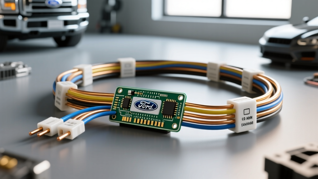
Advanced Architecture of the F-150 License Plate Lighting Circuit
The Ford F-150 license plate light wiring harness is not a simple switched 12-volt loop. In modern generations (specifically the 2015–2020 13th Gen and 2021+ 14th Gen platforms), the exterior lighting circuit is managed by the Body Control Module (BCM). The BCM utilizes solid-state Field Effect Transistors (FETs) to control power delivery, monitor current draw, and execute Pulse Width Modulation (PWM) for the signature 'fade-in' lighting effect. When diagnosing or repairing the license plate lamp harness, technicians must treat the circuit as a data-monitored network rather than a basic copper wire.
Because the license plate lamps are wired in parallel with the rear tail/parking lamps, a fault in the license plate harness branch—such as galvanic corrosion, a chafed ground, or an aftermarket LED mismatch—can trigger a BCM fault code, illuminate a dashboard warning, or even cause the BCM to shut down the entire rear park lamp circuit to protect its internal FETs.
Wiring Specifications, Routing, and BCM Pinout Chart
Understanding the precise routing and specifications of the harness is critical for accurate diagnosis. The harness originates at the BCM, passes through the cab-to-bed pass-through grommet behind the driver-side rear cab mount, and integrates into the rear body harness near the spare tire hoist before branching off to the rear bumper valance.
| Circuit Function | Wire Color (Ford Standard) | AWG / Metric | Origin / Termination | System Role |
|---|---|---|---|---|
| Park / License Feed | Brown (BN) or BN/WH | 18 AWG (0.82mm²) | BCM C2280B Pin 14 | 12V PWM-controlled positive feed |
| Chassis Ground | Black (BK) | 18 AWG (0.82mm²) | Ground Point G402 (Rear Bed) | Low-resistance return path |
| Inline Connector | N/A | N/A | 14-Pin Bed-to-Bumper Harness | Service disconnect / failure point |
Note: Wire colors may vary slightly by exact model year and trim (e.g., XL vs. Platinum). Always verify with a factory wiring diagram before cutting or splicing. All primary automotive cable must meet the SAE J1128 Low Tension Primary Cable Standard for temperature and insulation abrasion resistance.
Common Failure Modes in the Rear Harness
The license plate harness branch is uniquely vulnerable due to its exposure to road spray, salt, and physical debris. The most frequent failure modes include:
- Tailgate Pass-Through Boot Intrusion: The rubber grommet where the harness transitions from the bed to the bumper valance degrades over time, allowing capillary water action to wick moisture into the 2-pin weatherpack connector.
- Galvanic Corrosion: When moisture meets the copper terminals and dissimilar metals in the socket, green verdigris forms, increasing resistance. This voltage drop tricks the BCM into reading an 'open circuit'.
- Chafing at the Spare Tire Hoist: The main harness routing near the spare tire carrier lacks adequate loom protection on some early 13th-gen models, leading to insulation wear and short-to-ground events.
Diagnostic Decision Tree: License Plate Lamp Faults
Use this structured diagnostic tree when facing a DTC such as B108B:11 (License Plate Lamp Circuit Open / Short to Ground) or a physical lamp failure.
- Symptom: License plate lights are completely dead; dash displays 'Check Lighting' warning.
- Test 1: Probe the BN (Brown) wire at the lamp socket with a digital multimeter (DMM) referenced to battery negative.
- Result A (0 Volts): Circuit is open or BCM has tripped FET protection. Move to Test 2.
- Result B (11.5V - 12.5V): Power is present. Fault is in the ground circuit or the bulb itself. Inspect Ground Point G402 for bedliner paint over-spray or corrosion.
- Test 2: Clear the BCM DTCs using an OBD2 scanner and command the park lamps ON.
- Result A (Power returns briefly, then drops to 0V): The BCM is detecting an over-current event (short to ground) or massive inrush current. Inspect the harness for pinched wires near the bumper valance.
- Result B (No power returns): The BCM detects an open circuit. Check the 14-pin inline bed-to-bumper connector for backed-out pins or corrosion.
- Test 1: Probe the BN (Brown) wire at the lamp socket with a digital multimeter (DMM) referenced to battery negative.
- Symptom: License plate lights flicker rapidly or pulse (when using aftermarket LEDs).
- Cause: The BCM is utilizing PWM (Pulse Width Modulation) to fade the lights in, or it is rapidly cycling power because the LED's low current draw falls below the BCM's FET 'bulb-out' detection threshold.
- Fix: Install a PWM smoothing decoder or CANBUS adapter harness in parallel to simulate the resistive load of a standard 194 incandescent bulb (approx. 0.25A draw).
Harness Repair Protocol and USCAR Crimping Standards
When the license plate pigtail is corroded beyond cleaning, cutting and splicing a new Motorcraft Electrical Pigtail is required. Soldering is strictly prohibited in modern Ford exterior harnesses due to the creation of a rigid stress point that will eventually fracture under vibration. You must use open-barrel crimps and adhere to USCAR-21 specifications.
- Wire Stripping: Use a precision wire stripper calibrated for 18 AWG. The strip length must be exactly 5.5mm to 6.0mm. Do not nick the copper strands, as this reduces the cross-sectional area and creates a localized hot spot.
- Terminal Crimping: Use a ratcheting open-barrel crimp tool (such as the TE Connectivity HD-20 or equivalent). The crimp must exhibit a proper 'bellmouth' on both the front and rear of the terminal to prevent the wire from slicing against sharp terminal edges. According to SAE standards, an 18 AWG crimp must withstand a minimum pull-test force of 40 lbs without the wire slipping from the barrel.
- Sealing: Insert the terminal into the new 2-pin TE Connectivity Automotive Sealed Connector housing until you hear a distinct click. Perform a gentle pull-back test to ensure the terminal locking lance is engaged.
- Environmental Protection: Slide dual-wall, adhesive-lined heat shrink tubing over the splice joint. Apply heat evenly until the adhesive purges from the edges, creating a watertight seal against road salt and moisture.
LED Upgrades: Overcoming BCM FET Logic
Upgrading the F-150 license plate lamps to LED is a common modification, but it frequently causes electrical headaches. A standard 194 incandescent bulb draws roughly 3 watts (0.25 Amps). An equivalent LED bulb draws less than 0.05 Amps.
The Ford BCM monitors the voltage drop across an internal shunt resistor on the high-side FET to calculate current draw. If the BCM expects 0.25A but only reads 0.05A, its internal logic assumes the filament has broken (an open circuit). Consequently, the BCM will log a soft DTC, trigger a dash notification, and may hyper-flash or cut power entirely.
The Engineering Solution: Do not simply splice in basic load resistors, which generate excessive heat and pose a fire risk near the plastic bumper valance. Instead, utilize a dedicated CANBUS decoding harness adapter. These adapters contain surface-mount ICs and capacitors that store and release current to mimic the exact inrush curve and steady-state draw of a tungsten filament, satisfying the BCM's FET monitoring logic without generating dangerous thermal loads. Always verify the adapter's IP67 waterproof rating before installing it in the exterior license plate harness cavity.