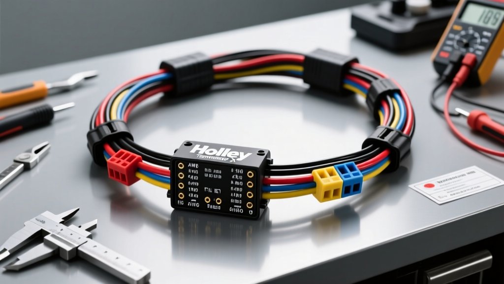
Holley Terminator X Wiring Harness Architecture Overview
The Holley Terminator X engine management system utilizes a highly modular, speed-density capable wiring harness architecture designed to simplify complex EFI swaps. Unlike the older HP and Dominator platforms, the Terminator X harness topology relies on a centralized ECU bulkhead that breaks out into dedicated sub-harnesses for injectors, ignition coils, and specific OEM sensor configurations (such as GM LS, Ford Coyote, or Chrysler Hemi). Understanding the precise pinout, wire gauge (AWG) requirements, and connector standards is critical for custom chassis integration, troubleshooting EMI (Electromagnetic Interference) issues, and fabricating extension harnesses for engine-set-back applications.
This technical specification reference details the core electrical parameters of the universal Terminator X main harness, sensor sub-harnesses, and Bosch 4.9 Wideband O2 integration. All wire color codes and AWG specifications align with Holley's proprietary EFI color scheme and SAE J1128 low-tension primary cable standards for under-hood automotive environments.
Main ECU Power & Ground Distribution
Proper power and ground routing is the most common failure point in aftermarket EFI installations. The Terminator X ECU requires dedicated, fused battery power and a clean ignition-switched trigger. Grounding must be executed directly to the engine block or chassis grounding stud using a minimum of 10 AWG wire to prevent voltage drop under high-load alternator charging conditions.
| Pin ID | Function | Wire Color | AWG | Connector / Notes |
|---|---|---|---|---|
| A1 | +12V Battery (Constant) | Red | 12 AWG | Requires 30A Maxi-Fuse, direct to battery + |
| A2 | +12V Ignition (Switched) | Pink | 16 AWG | Triggered via ignition switch or ECU relay |
| A3 | Main ECU Power Ground | Black | 12 AWG | Must terminate to clean engine block metal |
| A4 | Sensor Reference Ground | Black/White | 18 AWG | Isolated ground for 5V analog sensors |
| A5 | ECU Main Relay Trigger | White/Red | 18 AWG | Low-side driver to control main EFI relay |
Integration Note: Never share the ECU Main Power Ground (A3) with high-amperage accessories such as electric cooling fans or fuel pumps. Doing so will introduce ground bounce, which manifests as erratic idle control and corrupted MAP sensor readings.
Universal Sensor Input Specifications
The Terminator X relies on a standardized 5V reference and signal return topology for analog sensors. When extending harnesses for custom turbo manifolds or remote-mounted throttle bodies, use shielded 20 AWG wire for all analog signal lines to prevent alternator whine and RF interference from penetrating the ECU's ADC (Analog-to-Digital Converter).
| Sensor | 5V Reference | Signal Wire | Sensor Ground | Connector Type |
|---|---|---|---|---|
| Intake Air Temp (IAT) | N/A (Thermistor) | Light Blue | Light Blue/Black | Metri-Pack 150 (2-Pin) |
| Coolant Temp (CTS) | N/A (Thermistor) | Light Green | Light Green/Black | Metri-Pack 150 (2-Pin) |
| Throttle Position (TPS) | Brown | Dark Blue | Brown/Black | Weather-Pack (3-Pin) |
| Manifold Pressure (MAP) | Brown/White | Dark Blue/White | Brown/Black | Weather-Pack (3-Pin) |
Thermistors (IAT and CTS) operate on a resistance-based voltage divider circuit. The ECU supplies a 5V pull-up through an internal resistor. As coolant or air temperature rises, resistance drops, pulling the signal voltage closer to 0V. Extending these wires beyond 36 inches requires solder-seal splices and adhesive-lined heat shrink to prevent moisture-induced resistance changes, which the ECU will interpret as false temperature spikes.
Bosch 4.9 Wideband O2 Sensor Integration
The Terminator X natively supports the Bosch LSU 4.9 Wideband O2 sensor. Unlike older narrow-band sensors, the 4.9 utilizes a complex multi-cell architecture requiring precise wiring to the ECU's dedicated wideband controller harness adapter. Miswiring the wideband harness will instantly destroy the sensor's internal calibration resistor and pump cell.
- Pin 1 (White): Heater + (12V Switched via ECU relay)
- Pin 2 (Grey): Heater - (ECU PWM Ground Control)
- Pin 3 (Black): Pump Cell Current
- Pin 4 (Red): Reference Cell Voltage
- Pin 5 (Yellow): Calibration Resistor (Do NOT extend or splice)
- Pin 6 (Blue): Sense / Trim
Critical Warning: The calibration resistor wire (Yellow, Pin 5) is laser-trimmed at the Bosch factory to match the specific oxygen pump cell characteristics of that exact sensor. If you must extend the wideband harness to reach the ECU cabin pass-through, you must cut and extend the entire harness from the sensor connector plug. Never cut the yellow wire between the sensor and its immediate adapter plug.
Ignition & Injector Sub-Harness Routing
The Terminator X utilizes low-side drivers for both fuel injectors and ignition coils. This means the injectors and coils receive constant +12V from the main EFI relay, and the ECU completes the circuit by providing a pulsed ground.
Injector Sub-Harness
Injector drivers are rated for high impedance (saturated) and low impedance (peak and hold) injectors. The sub-harness utilizes 16 AWG TXL wire terminated with Metri-Pack 280 connectors.
- Power Feed: Pink (12V+ from EFI Relay)
- ECU Control: White (Bank 1), White/Black (Bank 2) - specific cylinder identifiers feature unique tracers.
Ignition Coil Sub-Harness
Modern LS and Coyote coil-on-plug (COP) systems draw significant current during the dwell phase. The Holley coil sub-harness uses 16 AWG wire to prevent voltage drop during cranking.
- Coil +: Pink/White (12V Ignition)
- Coil Ground: Black (Local engine block ground)
- Trigger Signal: Specific color per cylinder (e.g., Yellow, Yellow/Black)
CAN Bus & Shielding Requirements
For digital dash integration (such as the Holley EFI Digital Dash or aftermarket Racepak/AEM CAN gauges), the Terminator X utilizes a standard CAN 2.0B bus operating at 500 kbps.
- CAN High: Green
- CAN Low: Green/White
Diagnostic Failure Modes: Cam/Crank Sync Loss
A common issue during initial harness integration is a 'No Sync' or 'Cam/Crank Sync Error' in the Terminator X software. This is rarely an ECU failure and almost always a harness or sensor configuration issue.
| Symptom | Probable Cause | Harness Verification Step |
|---|---|---|
| Signal present but noisy/jittery | VR Sensor Shield Grounded at Sensor | Verify shield drain wire is grounded ONLY at the ECU connector, not at the sensor pigtail. |
| Signal drops out during cranking | Voltage Drop on 12V+ Sensor Feed | Measure voltage at sensor connector during crank. Must remain above 10.5V for Hall-Effect sensors. |
| Cam signal offset by 180 degrees | Incorrect Sensor Polarity / Wiring | Swap Signal and Ground wires on VR cam sensor; Hall sensors cannot be swapped without triggering a short. |
For Variable Reluctance (VR) crank sensors (common on older SBC/BBC and early Ford applications), the sensor generates an AC voltage signal. The Holley harness utilizes a shielded 2-wire cable for VR sensors. The shield drain wire must ONLY be grounded at the ECU end. Grounding the shield at both the sensor and the ECU creates a ground loop, allowing alternator stator noise to induce false trigger pulses, causing the ECU to advance or retard timing erratically at high RPM.