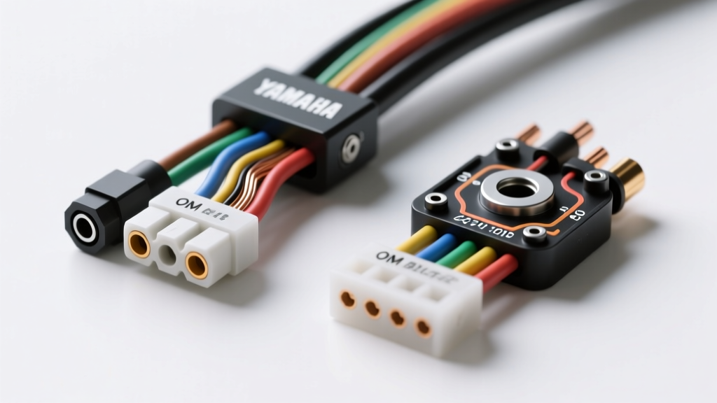
The YFS200 Electrical Ecosystem: Why Your Harness Matters
The Yamaha Blaster YFS200 (1987-2006) is legendary for its mechanical simplicity, but its electrical system is often the victim of age, neglect, and harsh off-road environments. The factory wiring harness was designed with 1980s-era PVC insulation and unsealed bullet connectors. After two decades of exposure to mud, water, and the intense radiant heat of the YFS200 expansion chamber, this insulation becomes brittle, leading to micro-fractures, short circuits, and notorious 'no-spark' conditions.
When restoring or upgrading a Blaster, selecting the correct Yamaha Blaster wiring harness is critical. A flawed harness will cause erratic idle, blown headlight bulbs, or complete ignition failure. In this comprehensive selection guide, we break down OEM replacements, aftermarket alternatives, and custom fabrication strategies, providing the exact wire gauges, color codes, and connector specifications you need to make an informed decision.
Head-to-Head: Yamaha Blaster Wiring Harness Options
Choosing the right harness depends on your budget, your desired level of factory originality, and your willingness to perform custom crimping. Below is a direct comparison of the three primary routes for YFS200 rewiring.
Option 1: Genuine Yamaha OEM Harness
Sourcing a New Old Stock (NOS) or genuine OEM replacement harness (such as part number 2TN-82590-10-00 for later models) guarantees perfect fitment and exact factory color coding. However, OEM harnesses are increasingly difficult to find and command a premium price. Furthermore, if you purchase a used OEM harness, you are inheriting the same aging PVC insulation and corroded Sumitomo connectors that caused your initial electrical failure.
Option 2: Aftermarket Replacement Harnesses
Brands like Caltric, Moose Racing, and TrailTech offer complete plug-and-play aftermarket harnesses. These are generally 40% to 60% cheaper than OEM equivalents. While they solve the immediate issue of broken wires, many budget aftermarket harnesses use undersized 20 AWG or 22 AWG wire for high-draw circuits and utilize low-grade brass bullet connectors instead of copper. This can lead to voltage drop across the stator-to-CDI circuit, resulting in a weak spark at high RPMs.
Option 3: Custom Fabricated / Rewire Kits
For the ultimate reliability, building a custom harness using automotive-grade TXL (cross-linked polyethylene) wire is the superior choice. TXL wire is rated for 125°C, making it highly resistant to the exhaust header heat that plagues the Blaster's right-side wiring routing. By pairing 18 AWG TXL wire with sealed Deutsch or insulated copper bullet connectors, you create a harness that vastly outlasts both OEM and budget aftermarket options.
YFS200 Stator & CDI Wire Color Specification Chart
Whether you are testing an existing harness or fabricating a new one, adhering to the Yamaha YFS200 Blaster Service Manual color codes is essential for troubleshooting and ensuring the CDI receives the correct voltage signals. Below is the definitive wire specification chart for the Blaster's primary ignition and lighting circuits.
| Circuit Function | Factory Color Code | Recommended AWG | Wire Type | Destination / Component |
|---|---|---|---|---|
| Source Coil (Trigger) | White/Red | 18 AWG | TXL / Shielded | Stator to CDI (Pin 2) |
| Ignition Coil (Primary) | Black/Red | 16 AWG | TXL | Stator to CDI (Pin 1) |
| Engine Kill Switch | Black/Yellow | 18 AWG | TXL | CDI (Pin 3) to Ground |
| Lighting Coil | Yellow | 14 AWG | TXL | Stator to Regulator / Headlight |
| Main Ground | Black | 14 AWG | TXL | CDI, Stator, Frame Ground |
| CDI to Ignition Coil | Orange | 16 AWG | TXL | CDI (Pin 5) to Coil Primary |
CDI Connector Pinout & Signal Verification
The Blaster utilizes a 6-pin Sumitomo HM series connector at the CDI unit. A common failure mode in aftermarket harnesses is reversed pinouts or poor terminal retention. When verifying your harness, use a digital multimeter to check the following pinout configuration:
- Pin 1 (Black/Red): Receives high-voltage AC from the stator's ignition coil. Should read 0.36 to 0.44 ohms resistance at the stator side.
- Pin 2 (White/Red): Receives the trigger signal from the source coil. Should read 730 to 990 ohms resistance.
- Pin 3 (Black/Yellow): Kill switch circuit. When the tether or key switch is engaged, this pin shorts to ground, collapsing the CDI's internal capacitor and killing the spark.
- Pin 4 (Black): Main CDI ground. Must have less than 0.5 ohms of resistance to the bare frame.
- Pin 5 (Orange): High-voltage output from the CDI to the external ignition coil.
- Pin 6: Typically vacant or utilized as a secondary ground on specific late-model TCI units.
Common YFS200 Harness Failure Modes & Troubleshooting
Understanding how the factory Yamaha Blaster wiring harness fails will help you route and protect your new installation. Based on extensive field data and SAE J1128 Low Tension Primary Cable Standards, here are the most frequent points of failure:
1. Voltage Regulator Ground Starvation
On 1998 and newer Blasters equipped with a taillight and voltage regulator, the regulator relies on the wiring harness ground rather than a dedicated case ground. If the 14 AWG black ground wire in the harness develops resistance due to corrosion, the regulator cannot shunt excess AC voltage. This results in voltage spikes that instantly blow the headlight and taillight bulbs. Fix: Always run a dedicated 14 AWG ground wire directly from the regulator mounting bolt to the engine block.
2. Expansion Chamber Heat Degradation
The factory harness routes dangerously close to the right-side exhaust expansion chamber. Over time, the PVC insulation melts or hardens, exposing the copper strands. When the bare Yellow lighting coil wire touches the frame, it shorts the lighting circuit, causing the stator to overheat and fail. Fix: Wrap the right-side harness loom in reflective fiberglass heat-sleeving and secure it with stainless steel zip ties to maintain a minimum 2-inch clearance from the exhaust.
3. Steering Stem Chafing
The main harness passes through the steering stem bearing area to reach the handlebars. Turning the handlebars left and right causes the harness to rub against the sharp inner edges of the frame tube. Fix: Install a rubber grommet or spiral wrap the harness in split-loom tubing with electrical tape seals before feeding it through the steering stem.
Connector Selection: Upgrading Beyond the Factory Bullet
The Yamaha Blaster stator outputs rely heavily on 2.5mm bullet connectors. The factory used uninsulated brass bullets, which are highly prone to oxidation and 'green crust' corrosion when exposed to water crossings. When building or repairing your harness, discard standard hardware-store brass bullets.
Instead, source insulated copper bullet connectors with nylon or PVC sleeves. For the ultimate waterproof seal, use marine-grade heat-shrink bullet connectors featuring a polyolefin outer shell and an inner layer of hot-melt adhesive. When crimping, always use a ratcheting wire crimper calibrated for 18-16 AWG terminals to ensure the wire strands are compressed without cutting into the copper core, which would increase electrical resistance and create a localized hot spot.
Final Verdict: Which Harness Should You Choose?
If you are performing a museum-quality restoration and budget is not a concern, tracking down a genuine OEM Yamaha Blaster wiring harness is the only way to maintain factory authenticity. However, for riders who actually race, trail ride, or subject their YFS200 to harsh conditions, the OEM harness is a relic of outdated materials.
For 90% of Blaster owners, a custom-fabricated harness using 18 AWG and 16 AWG TXL wire paired with marine-grade heat-shrink connectors is the undisputed best choice. It costs roughly the same as a mid-tier aftermarket harness but offers double the current-carrying capacity, superior heat resistance, and a sealed electrical environment that will easily outlast the ATV itself. Take the time to map your pinouts, solder critical ground junctions, and route your loom away from the exhaust, and your Blaster's electrical system will be virtually bulletproof.