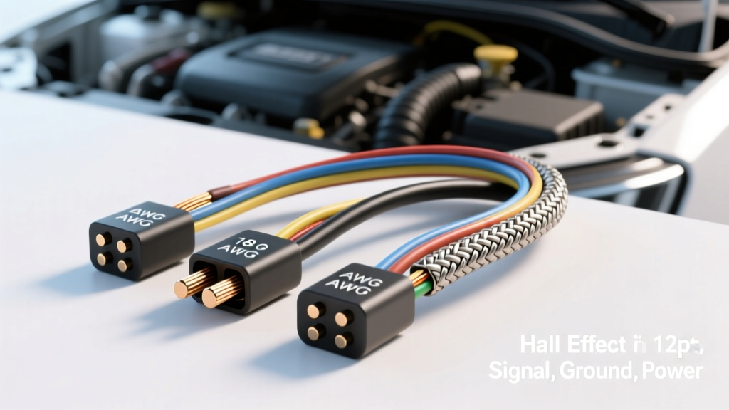
Introduction to the 3 Wire Camshaft Position Sensor Wiring Harness
In modern engine management and complex engine swap scenarios, the 3 wire camshaft position sensor wiring harness is a critical conduit for precise valvetrain timing data. Unlike older 2-wire Variable Reluctance (VR) sensors that output an analog sine wave, 3-wire configurations are reserved for Hall Effect and Magneto-Resistive sensors. These active sensors require a dedicated power source, a ground reference, and a signal output wire to transmit a crisp, digital square wave directly to the Engine Control Unit (ECU).
Whether you are fabricating a custom harness for a GM LS/LT swap, integrating a Ford Coyote engine into a classic chassis, or diagnosing an OEM driveability concern, understanding the exact architecture of this harness is non-negotiable. A flaw in the 3 wire camshaft position sensor wiring harness will result in catastrophic phasing errors, sequential fuel injection failure, and Variable Valve Timing (VVT) limp-mode defaults.
Hall Effect vs. Magneto-Resistive: Why 3 Wires?
Before cutting and stripping wire, it is vital to understand the sensor topology. A 3-wire harness powers an active internal IC (Integrated Circuit) within the sensor housing.
- Hall Effect Sensors: Utilize a magnetic field and a semiconductor to generate a voltage differential. They typically require a 5V or 12V reference and output a 0V to 5V (or 12V) square wave.
- Magneto-Resistive Sensors: Measure the change in electrical resistance caused by a passing reluctor wheel. These are highly sensitive and often require shielded harnesses to prevent Electromagnetic Interference (EMI) from adjacent ignition coil packs.
Because the ECU relies on the sharp rising and falling edges of this digital signal to calculate exact camshaft phasing, the integrity of the wiring harness—specifically its shielding and terminal crimp quality—is paramount.
Wire Gauge, Insulation, and Routing Specifications
When building or repairing a 3 wire camshaft position sensor wiring harness, selecting the correct Automotive Wire Specification is critical for under-hood survival. Standard PVC wire will melt and short out against exhaust manifolds or EGR tubes.
AWG and Material Requirements
| Parameter | Specification | Technical Rationale |
|---|---|---|
| Wire Gauge (AWG) | 18 AWG or 20 AWG | Sufficient for low-amperage signal/reference circuits while maintaining flexibility for tight loom routing. |
| Insulation Type | TXL, GXL, or SXL (Cross-Linked Polyethylene) | Withstands continuous ambient temperatures up to 125°C (TXL) or 150°C (GXL/SXL) without degrading. |
| Shielding | Braided Copper with Aluminum/Mylar Wrap | Mandatory for Magneto-Resistive sensors to block high-frequency EMI from ignition coils and alternators. |
| Connector Type | Delphi Metri-Pack 280 or Bosch Jetronic | Provides high-temperature nylon housings with secondary silicone mat seals for IP67 waterproofing. |
Standard Pinout Configurations: GM LS/LT and Ford Modular
Pinouts vary drastically between manufacturers. Miswiring the reference voltage into the signal return will instantly fry the internal Hall IC or damage the ECU's internal pull-up resistors. Below are the standard configurations for the most common V8 swap platforms.
GM Gen III/IV LS (24x/58x Reluctor) Cam Sensor Pinout
GM LS engines utilize a 12V reference system for the camshaft position sensor. The connector is typically a Delphi Metri-Pack 150 or 280 series 3-way female housing.
- Pin A (Reference Voltage): 12V (Typically Pink wire). Fed directly from the ECU's internal or external switched 12V driver.
- Pin B (Signal Output): Digital Square Wave (Typically Brown or Brown/White wire). Pulls to ground internally via the sensor's open-collector transistor.
- Pin C (Low Reference/Ground): Sensor Ground (Typically Black/White wire). Must be routed back to the ECU's dedicated sensor ground plane, NOT the engine block.
Ford Coyote / Modular (Hall Effect) Cam Sensor Pinout
Ford's architecture relies on a 5V reference system. The connector is often a Bosch-style or Ford-specific 3-way weather-pack.
- Pin 1 (Reference Voltage): 5V (Typically Orange/Light Green). Supplied by the PCM's 5V voltage regulator.
- Pin 2 (Signal Return): Digital Signal (Typically Dark Green/Orange).
- Pin 3 (Signal Return Ground): Shared Sensor Ground (Typically Gray/Red).
Always verify with a factory service manual or a verified Helm Inc. wiring diagram before applying power to any aftermarket or OEM harness.
Advanced Harness Fabrication: Shielding and Ground Loops
The most common cause of unexplained cam/crank correlation codes (such as GM P0016 or Ford P0340) in engine swaps is EMI induction on the signal wire. Ignition coils generate massive voltage spikes (up to 40,000V) that can induce a phantom voltage in an unshielded cam sensor signal wire, tricking the ECU into seeing a false reluctor tooth.
Proper Shield Drain Wire Termination
If your 3 wire camshaft position sensor wiring harness utilizes shielded cable, the shield drain wire must be terminated correctly to avoid creating a ground loop.
- Ground at the ECU Only: The braided shield drain wire should ONLY be grounded at the ECU connector shell or the ECU's dedicated shield ground pin.
- Isolate at the Sensor: At the sensor connector side, the shield must be trimmed, folded back, and sealed with heat shrink. If the shield touches the engine block or the sensor's metal housing, it creates an antenna that will broadcast alternator whine and ignition noise directly into the ECU.
- Use Kapton Tape: Wrap the exposed signal wires in Kapton (polyimide) tape before sliding the braided shield over them to prevent microscopic short circuits against the drain wire.
Terminal Crimping and Connector Seating
A flawless schematic is useless if the terminal crimps are poor. For Delphi Metri-Pack 280 terminals, the wire crimp and insulation crimp must be distinct. Use a ratcheting crimp tool calibrated for the specific terminal series. According to SAE J2360 standards for automotive electrical connectors, a properly crimped 18 AWG terminal should withstand a minimum pull-force of 15 lbs without the wire separating from the brass terminal. Furthermore, always ensure the primary and secondary silicone seals are fully seated to prevent capillary action from drawing moisture into the ECU cavity.
Oscilloscope Diagnostics: Reading the Square Wave
When diagnosing a suspected harness failure, a multimeter is insufficient. You must use a digital storage oscilloscope (DSO) to view the signal integrity. Connect Channel A to the signal wire and Channel B to the crankshaft sensor signal.
Waveform Analysis Criteria
- Amplitude: The high state should exactly match the reference voltage (e.g., 4.9V to 5.1V for Ford, 11.5V to 12.5V for GM). A high state of 3.5V on a 5V circuit indicates excessive voltage drop in the harness or a failing ECU pull-up resistor.
- Edge Ringing: The vertical rising and falling edges of the square wave should be crisp. If you see 'ringing' (high-frequency oscillation on the edges), your harness lacks proper shielding or the ground return has excessive impedance.
- Dropouts: Any dip to 0V outside of the normal reluctor gap indicates a chafed wire shorting to the engine block during engine torque roll.
For comprehensive waveform examples and diagnostic matrices, refer to the Pico Technology Automotive Waveform Library, which provides empirical baseline captures for nearly all 3-wire Hall Effect configurations.
Summary for Engine Swap Integration
Integrating a 3 wire camshaft position sensor wiring harness into a standalone ECU (like a Holley Terminator X or Haltech Elite) requires meticulous attention to the ECU manufacturer's specific pinout matrix. Never assume wire colors match between the engine harness and the standalone ECU harness. Always map the functions (12V/5V Ref, Signal, Ground), utilize 18 AWG TXL cross-linked wire, implement single-point shield grounding, and verify the digital square wave with an oscilloscope before attempting to start the engine. By adhering to these advanced electrical principles, you ensure precise VVT control, flawless sequential injection, and long-term harness reliability in the harshest under-hood environments.