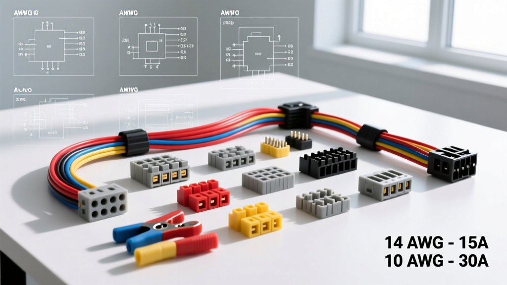
Architectural Overview of Hot Rod Electrical Systems
Designing a custom hot rod wiring harness requires a fundamental shift from OEM point-to-point routing to a centralized, modular topology. Unlike modern production vehicles that rely on multiplexed CAN-bus networks and solid-state power distribution modules, traditional hot rod and street rod builds utilize discrete copper circuits managed by a centralized fuse block. This reference outlines the exact technical specifications, AWG sizing parameters, and connector standards required to build a reliable, high-current hot rod wiring harness capable of supporting modern EFI (Electronic Fuel Injection) and high-output charging systems.
Wire Insulation Standards: SAE J1128 Compliance
Standard PVC-insulated wire is unacceptable for under-hood hot rod applications due to its low melting point and poor abrasion resistance. Professional hot rod wiring harness fabrication mandates the use of cross-linked polyethylene (XLPE) insulation. According to the SAE J1128 Standard, builders should specify GXL, TXL, or SXL wire types.
- GXL (General Cross-Linked): The industry standard for hot rods. Features a thin wall for reduced harness bulk and a continuous temperature rating of 125°C.
- TXL (Thin Cross-Linked): Used in tight firewall pass-throughs where space is at an absolute premium. Rated to 125°C.
- SGT (Commercial Battery Cable): Mandatory for starter and alternator main feeds. Must be pure copper, never Copper-Clad Aluminum (CCA), to prevent voltage drop and thermal runaway.
Primary Circuit AWG Sizing and Load Specifications
Wire gauge selection must account for both the continuous amperage draw and the physical length of the circuit to mitigate voltage drop. The following table serves as a baseline specification for a standard 21-circuit hot rod wiring harness utilizing a front-mounted fuse block.
| Circuit Function | Max Load (Amps) | Recommended AWG | Fuse Rating (ATO/Mini) | Wire Type |
|---|---|---|---|---|
| Starter Solenoid Feed | 250A+ (Cranking) | 1/0 AWG | 175A Mega-Fuse at Battery | SGT Weld Cable |
| Headlights (Halogen 55W) | 10A per pair | 10 AWG (Direct) / 14 AWG (Relay) | 20A | GXL |
| EFI Fuel Pump (In-Tank 255LPH) | 15A - 18A | 10 AWG | 20A | GXL |
| ECU Main Power & Ground | 10A (Spikes to 15A) | 12 AWG | 15A | GXL (Shielded for sensors) |
| Ignition System (LS/HEI Coils) | 12A | 12 AWG | 15A | GXL |
| Electric Cooling Fan (Dual 16") | 35A - 45A | 8 AWG (Relay Feed) | 50A (Maxi Fuse) | GXL |
| HVAC Blower Motor (Vintage Air) | 18A | 10 AWG | 20A | GXL |
Voltage Drop Calculations for Long Runs
In a 1932 Ford or 1957 Chevy with a trunk-mounted battery, the positive and negative cable runs can exceed 18 feet. Voltage drop must be calculated using the formula: VD = (2 x K x I x L) / CM, where K is the resistivity of copper (12.9 ohms per mil-foot), I is current, L is one-way length, and CM is the circular mil area of the wire. For a trunk-mounted battery supplying a 200A starter draw over 18 feet, 2 AWG wire will result in a 2.8V drop (leaving only 9.2V at the solenoid). Upgrading to 1/0 AWG (105,600 CM) reduces the drop to 0.78V, ensuring reliable cranking of high-compression V8 engines.
High-Current Load Management: ISO Mini Relay Integration
A properly engineered hot rod wiring harness never routes high-current loads (headlights, fuel pumps, cooling fans) through the dashboard switches. Switches are used solely to trigger relays. The standard Bosch-style ISO Mini 5-pin relay is the backbone of hot rod power distribution.
Standard 5-Pin Relay Pinout Specifications
- Pin 30 (Common): Fused +12V battery feed from the main distribution bus. Requires 10 AWG or 12 AWG wire depending on load.
- Pin 85 (Coil Ground): Ground connection for the internal electromagnetic coil. Route to a clean chassis ground via 14 AWG or 16 AWG.
- Pin 86 (Coil Trigger): +12V switched trigger from the dashboard toggle or push-button switch. 16 AWG wire is sufficient as coil draw is typically under 150mA.
- Pin 87 (Normally Open - NO): Output to the load (e.g., fuel pump positive terminal). Carries the full amperage of the load.
- Pin 87a (Normally Closed - NC): Unused in standard hot rod applications, but occasionally utilized for dual-function lighting circuits or anti-theft fuel pump kill switches.
Connector Systems: Weather-Pack vs. DEUTSCH DT
Selecting the correct connector system is critical for under-hood reliability. Vibration, thermal cycling, and moisture ingress are the primary failure modes in hot rod harnesses.
Delphi Weather-Pack Series
The Weather-Pack system is the legacy standard for hot rod builds. It features cylindrical pins and sockets with secondary silicone seals. While adequate for low-vibration areas (tail lights, interior dash pods), the Weather-Pack system is prone to terminal fretting corrosion in high-vibration zones like engine-mounted sensors. Maximum continuous current is 20A per cavity.
TE Connectivity DEUTSCH DT Series
For engine bay routing, EFI sensor pigtails, and transmission solenoid packs, the TE Connectivity DEUTSCH DT Series is the mandatory specification. The DT series utilizes a solid thermoplastic housing with integrated rear grommets and wedge-locks that prevent terminal back-out.
- Contact Size: Size 16 (accommodates 14-20 AWG wire).
- Current Rating: 13A continuous per contact.
- Crimp Specification: Requires a precision open-barrel crimp tool. The crimp height for 16 AWG wire in a Size 16 contact must be exactly 1.35mm ± 0.05mm to achieve the required 45 lb pull-test retention force without severing copper strands.
Grounding Hierarchy and Chassis Return Paths
Grounding is the most frequently overlooked aspect of hot rod wiring harness fabrication. A floating ground or high-resistance chassis return will cause ECU sensor skew, erratic gauge behavior, and alternator diode failure. Professional builders follow a strict star-grounding hierarchy, avoiding daisy-chained ground loops.
Mandatory Grounding Specifications
- Engine Block to Chassis: Minimum 1/0 AWG flexible braided copper or SGT welding cable. Must connect from a clean, bare-metal point on the cylinder head or block to a dedicated, paint-free chassis stud.
- Alternator Case to Engine: Alternator housings must have a dedicated ground strap (minimum 8 AWG) to the engine block. Relying on the alternator mounting brackets for the return path often results in voltage drop due to rust or powder-coating on the bracket surfaces.
- Cab to Chassis: 8 AWG or 6 AWG wire connecting the steel body tub to the main frame rail. Essential for interior dome lights, dash gauges, and HVAC blower motors.
- Fuel Cell / Tank to Chassis: 10 AWG ground strap required to prevent static accumulation and ensure accurate fuel sender resistance readings.
For comprehensive grounding layouts and fuse block placement strategies, builders frequently reference the Painless Performance Technical Manuals, which provide exact chassis penetration and grommet sizing for classic truck and car frames.
Alternator Excitation and Sense Wire Routing
Modern hot rods utilizing GM CS130, CS144, or Denso-style high-output alternators require precise excitation wiring. While "1-wire" alternators are popular for their simplicity, they suffer from poor low-RPM charging and inaccurate voltage regulation because they sense voltage at the alternator output terminal, not the battery.
3-Wire Alternator Pin Configuration (GM CS Series)
- Output Terminal (BAT): Connects to the main battery positive or starter solenoid via 4 AWG or 2 AWG wire, protected by a 150A Mega-Fuse.
- Terminal L (Excitation/Lamp): Requires a 16 AWG wire routed to an ignition-switched 12V source. A 560-ohm resistor or a 12V incandescent indicator bulb must be placed in-line to limit initial inrush current and protect the alternator's internal voltage regulator diodes.
- Terminal S (Voltage Sense): The most critical pin for stable EFI voltage. A 12 AWG or 10 AWG wire must be routed from the 'S' terminal directly to the battery positive terminal or the main distribution bus. This forces the regulator to compensate for voltage drop across the entire hot rod harness, maintaining a steady 14.2V at the ECU and fuel injectors regardless of accessory load.
Harness Looming and Abrasion Protection
Once circuits are terminated and tested, the harness must be protected. Split-loom corrugated tubing is acceptable for interior cabin routing. However, under-hood harness sections must be wrapped in Tesa 51036 PET fleece tape or expandable braided nylon sleeving. Fleece tape provides superior abrasion resistance against aluminum intake manifolds and firewall sheet metal, while dampening the high-frequency vibration rattle common with rigid plastic looms. All firewall pass-throughs must utilize stepped rubber grommets sealed with dielectric grease to prevent moisture wicking into the cabin.