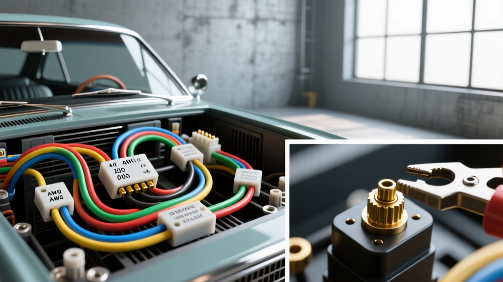
Why a Dedicated Air Conditioning Wiring Harness is Critical
When retrofitting modern climate control into classic vehicles, relying on the factory 40-year-old wiring is a recipe for catastrophic failure. Original equipment (OE) dash harnesses were engineered for minimal electrical loads, typically utilizing 16 AWG or 18 AWG wire for accessory circuits. Modern A/C compressor clutches, such as those found on Sanden SD7 or York-style pistons, require a minimum of 11.5 volts at the coil to engage reliably and prevent clutch slip. Voltage drop across degraded factory copper and undersized dash switches frequently reduces voltage at the clutch to 9.5V or lower, resulting in excessive heat, rapid coil degradation, and eventual compressor seizure. A dedicated, relay-driven air conditioning wiring harness bypasses the high-resistance factory dash switches, delivering full battery voltage directly to the compressor clutch and blower motor. This guide details the exact installation protocols, wire gauge requirements, and connector standards necessary to execute a flawless A/C harness installation.
Pre-Installation Preparation and Material Specifications
Automotive electrical environments demand materials that withstand extreme underhood temperatures, chemical exposure, and high-frequency vibration. Standard PVC wire is unacceptable for engine bay routing. According to the SAE J1128 standard, you must use GXL or TXL (cross-linked polyethylene) insulated wire, which offers a 125°C continuous operating temperature rating and a significantly thinner insulation wall for tighter bundle routing.
- Main Power Feed: 10 AWG GXL Red wire (rated for 30A continuous).
- Compressor Clutch Feed: 14 AWG GXL Dark Green wire (rated for 15A, though clutch draw is typically 3.5A to 4.5A; 14 AWG prevents voltage drop over long chassis runs).
- Ground Circuits: 10 AWG and 14 AWG GXL Black wire.
- Control/Signal Wires: 16 AWG GXL (Pink for 12V ignition/thermostat triggers, Blue for binary switch returns).
- Connectors: Delphi Weather-Pack (sealed with silicone ribbed seals) for all underhood connections; Metri-Pack 280 for cabin-side dash integrations.
- Terminals: Open-barrel, nickel-plated copper crimps. Avoid soldering underhood connections, as solder joints become brittle and fracture under engine harmonic vibration.
Air Conditioning Wiring Harness Circuit Architecture
A properly engineered air conditioning wiring harness utilizes a Bosch-style ISO 280 mini relay to isolate the high-current compressor clutch from the low-current dash thermostat switch. The thermostat and the binary/trinary safety switch are wired in series on the relay coil trigger circuit (Pin 86). If either the cabin thermostat opens (reaching target temperature) or the binary switch opens (detecting low refrigerant or dangerous high pressure), the relay coil loses ground or 12V trigger, instantly disengaging the compressor clutch.
ISO 280 Mini Relay Pinout and Wire Routing Table
| Relay Pin | Function | Wire Gauge | Wire Color | Destination / Source |
|---|---|---|---|---|
| Pin 30 | Main Power Input | 10 AWG | Red | Battery Positive (via 30A Maxi-Fuse) |
| Pin 87 | Switched Power Output | 14 AWG | Dark Green | Compressor Clutch Coil (+) |
| Pin 86 | Coil Trigger (12V+) | 16 AWG | Pink | Thermostat / Dash A/C Switch Output |
| Pin 85 | Coil Ground / Safety Switch | 16 AWG | Black / Blue | Binary Safety Switch to Chassis Ground |
Note: For systems utilizing a trinary switch (which includes an engine cooling fan trigger at ~254 PSI), a secondary relay is required. The trinary switch utilizes a 4-pin Weather-Pack connector. Refer to Vintage Air Technical Bulletins for specific trinary fan-relay integration diagrams.
Step-by-Step Installation Procedure
Step 1: Main Power and Fuse Block Integration
Begin by routing the 10 AWG Red main power wire from the battery positive terminal or the main starter solenoid stud. Install an inline 30A Maxi-Fuse holder within 18 inches of the power source to protect the harness in the event of a dead short. Use a closed-barrel ring terminal and a dedicated crimping tool (such as the TE Connectivity CERTI-CRIMP) to ensure a gas-tight connection. Secure the fuse block to the inner fender well using stainless steel hardware and nylon-insert lock nuts to prevent loosening from chassis flex.
Step 2: Firewall Penetration and Grommet Routing
Drill a 1.5-inch hole in the firewall, ensuring you are clear of the steering column, brake booster pushrod, and OE dash harnesses. Install a thick-wall EPDM rubber firewall grommet. Before feeding the harness through, apply a liberal coating of silicone dielectric grease to the wires and the inside of the grommet to prevent insulation abrasion. Once the harness is pulled through, seal the grommet edges with clear RTV silicone to prevent exhaust fumes and water intrusion into the cabin.
Step 3: Compressor Clutch and Binary Switch Connections
Route the 14 AWG Dark Green clutch wire along the passenger side inner fender, keeping it at least 4 inches away from exhaust headers to prevent TXL insulation melt-down. Secure the wire using split-loom tubing wrapped in Tesa 51036 fleece tape to eliminate harness rattle against the sheet metal. Connect the wire to the compressor clutch using a 1-pin Weather-Pack pigtail. The binary safety switch, typically mounted on the A/C manifold or drier, interrupts the Pin 85 ground circuit. Wire the 2-pin binary switch in series between the relay Pin 85 and a clean chassis ground. The binary switch will open the circuit if system pressure drops below 28 PSI (preventing compressor operation without refrigerant/oil) or exceeds 406 PSI.
Step 4: Grounding Protocols and Torque Specifications
Grounding is the most common failure point in aftermarket A/C harnesses. The compressor clutch ground and relay Pin 85 ground must terminate at bare, unpainted steel. Use a 1/4-inch (M6) or 5/16-inch (M8) ring terminal. Scrape away all paint and primer using a brass wire brush, apply a thin layer of anti-corrosion compound (such as Noalox), and secure the ground using a star washer and a hex flange nut. Torque the ground stud to 10 Nm (89 lb-in) to ensure maximum surface contact area and prevent voltage drop.
Blower Motor Resistor Integration and Thermal Management
If your harness kit includes blower motor control, pay strict attention to the resistor block wiring. The blower motor draws significant amperage (up to 15A on high speed). The power feed to the blower switch must be 12 AWG. The resistor block, which steps down voltage for Low and Medium fan speeds, generates immense heat. Mount the ceramic wirewound resistor block directly in the HVAC airbox so that the blower airflow cools the resistors. If the resistor block ground wire (typically 14 AWG Black) suffers high resistance, the blower motor will only operate on High speed, as the High-speed circuit bypasses the resistor block entirely via a separate internal relay.
Real-World Troubleshooting and Failure Modes
Even with meticulous installation, environmental factors can cause electrical anomalies. Use the following decision tree to diagnose common air conditioning wiring harness failures:
- Symptom: Compressor clutch engages but chatters rapidly or slips.
Cause: Severe voltage drop at the clutch coil or a failing clutch air gap.
Fix: Perform a voltage drop test. Place your multimeter probes directly on the clutch coil terminals while the engine is running and the A/C is commanded ON. If you read less than 11.5V, check the relay Pin 30 and Pin 87 connections. If voltage is 12.2V or higher, adjust the compressor clutch shim to reduce the air gap to 0.020" - 0.030". - Symptom: A/C system works for 10 minutes, then compressor disengages and will not re-engage until the vehicle cools down.
Cause: Thermal overload in the relay or binary switch tripping due to high head pressure.
Fix: Check the condenser fan operation. If the engine cooling fan is not pulling air through the condenser, high-side pressure will exceed 406 PSI, forcing the binary switch to open Pin 85. Verify the fan relay trigger wire from the trinary switch or ECU. - Symptom: Blower motor operates, but dash A/C switch gets unusually hot and smells like melting plastic.
Cause: The factory dash switch is being used to carry the full compressor clutch load instead of acting as a low-current signal trigger.
Fix: Immediately disconnect the battery. Rewire the harness so the dash switch only provides a 1.5A trigger signal to the ISO relay Pin 86. Never route high-amperage clutch loads through 40-year-old copper dash traces.
By adhering to SAE wiring standards, utilizing sealed Weather-Pack connectors, and isolating high-current loads via ISO relays, your air conditioning wiring harness will provide reliable, factory-grade climate control performance for decades. For further reading on automotive low-tension cable specifications, consult the SAE J1128 documentation.