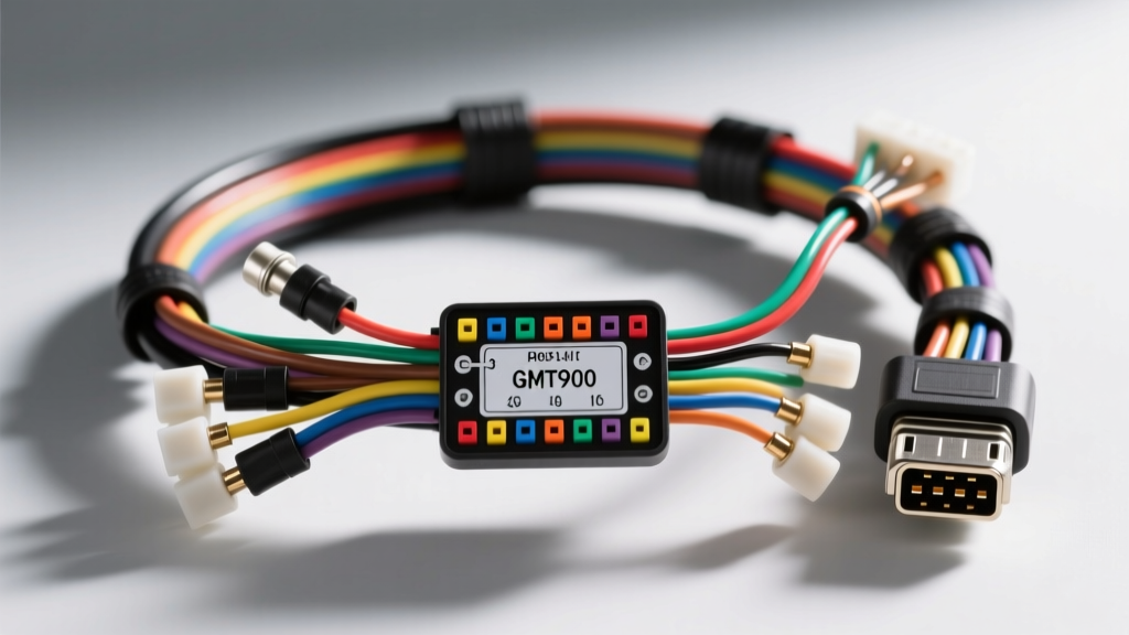
Introduction to ABS Sensor Harness Architecture
The anti-lock braking system (ABS) relies entirely on the integrity of the wheel speed sensor data to modulate brake pressure and prevent wheel lockup. At the core of this data transmission is the ABS wheel speed sensor wiring harness. This specialized wiring network routes critical low-voltage signals from the wheel hub assemblies back to the Electronic Brake Control Module (EBCM). Unlike standard chassis wiring, ABS harnesses are subjected to extreme articulation, high-velocity debris, water intrusion, and intense electromagnetic interference (EMI). A failure in the harness—whether a chafed wire, a corroded terminal, or a broken twisted pair—will immediately trigger a diagnostic trouble code (DTC) such as C0035 (Left Front Wheel Speed Sensor Circuit) and illuminate the ABS and traction control warning lamps.
In this complete wiring diagram walkthrough, we will dissect the architecture of modern active ABS sensor harnesses, using the widely serviced GM GMT900 platform (2007-2013 Silverado/Sierra) as our primary technical reference. We will cover pin configurations, wire gauge specifications, routing protocols, and advanced oscilloscope diagnostics.
Active vs. Passive Sensor Harness Requirements
Before tracing the diagram, it is vital to understand the difference between passive and active ABS systems, as this dictates the harness design. Older passive systems utilized Variable Reluctance (VR) sensors, which generated their own AC voltage signal as a toothed reluctor ring passed by the magnetic sensor tip. The harness for a VR sensor only needed to carry a generated AC signal back to the module.
Modern vehicles, including the GMT900 and most post-2005 platforms, utilize active magneto-resistive or Hall-effect sensors. Active sensors require a power supply from the EBCM to operate. Therefore, the ABS wheel speed sensor wiring harness must carry both a reference voltage (typically 5V to 12V) to the sensor and a modulated square-wave signal back to the module. Because these signals are highly sensitive to EMI from the ignition system and alternator, the harness wires are manufactured as a shielded twisted pair. Untwisting or improperly splicing these wires during a repair will destroy the common-mode noise rejection, leading to false ABS activation at low speeds.
GMT900 ABS Wheel Speed Sensor Wiring Harness: Pinout & Diagram Walkthrough
The GMT900 EBCM utilizes a multi-cavity connector, with specific pins dedicated to each wheel speed sensor circuit. The harness routes from the EBCM (located in the engine bay, typically driver-side near the master cylinder) through the main chassis bulkhead, splitting at the frame rails to reach each wheel well.
Front vs. Rear Sensor Harness Routing
The front ABS harness pigtails must accommodate the full steering sweep and suspension travel. The harness is secured to the steering knuckle and upper control arm using specific plastic loom clips and zip-ties. If the harness is routed too tightly, the steering lock will stretch and snap the 22 AWG copper strands inside the insulation. The rear harnesses route along the solid axle tubes, requiring a slack loop near the differential to account for suspension compression and axle articulation.
Technical Specifications: Wire Gauge, Shielding, and Connectors
Automotive signal wiring must adhere to strict resistance and voltage-drop thresholds. According to the SAE J1128 Standard for Low Tension Primary Cable, signal wires must maintain specific insulation thickness and thermal ratings to survive under-hood and under-carriage environments. Below is the specification chart for a standard GM active ABS wheel speed sensor harness.
| Wire Function | Color Code (GMT900 Example) | AWG Size | Circuit ID | Connector / Terminal Type |
|---|---|---|---|---|
| Left Front Signal High (Power) | Dark Green | 22 AWG | 6C01 | Metri-Pack 150 Sealed |
| Left Front Signal Low (Return) | Yellow | 22 AWG | 6C02 | Metri-Pack 150 Sealed |
| Right Front Signal High (Power) | Dark Blue | 22 AWG | 6C05 | Metri-Pack 150 Sealed |
| Right Front Signal Low (Return) | Brown | 22 AWG | 6C06 | Metri-Pack 150 Sealed |
| Harness Outer Shield / Drain | Bare Copper / Black Tracer | 20 AWG | N/A | Ring Terminal to Chassis |
Note: The Metri-Pack 150 series connectors utilize a silicone ribbed mat seal to prevent water ingress. The Terminal Position Assurance (TPA) lock must be fully seated; otherwise, vibration will back the terminal out of the cavity, causing an intermittent open circuit.
Step-by-Step Harness Testing & Diagnostic Walkthrough
When diagnosing a wheel speed sensor DTC, technicians often condemn the sensor itself without verifying the harness. As detailed in the Bosch Mobility Solutions ABS Diagnostics Guide, the harness is statistically more likely to fail than the solid-state sensor element. Follow this diagnostic sequence to isolate the fault.
1. Visual Inspection for Harness Chafing and Corrosion
Begin by tracing the harness from the wheel hub connector back to the first major chassis clip. Look for insulation wear where the harness rubs against the steering knuckle, brake caliper bracket, or suspension components. Inspect the connector cavity for green or white copper oxide corrosion. If the silicone mat seal is compromised, capillary action will draw water into the EBCM connector, destroying the module pins.
2. Multimeter Resistance and Continuity Checks
Disconnect the battery and unplug the EBCM connector to isolate the harness.
- Short to Ground Test: Set your digital multimeter (DMM) to Ohms. Measure from the harness-side signal pins (e.g., Dark Green and Yellow for LF) to a known good chassis ground. The reading should be OL (infinite). Any resistance indicates the harness insulation has worn through and is shorting to the frame.
- Continuity Test: Measure across the two harness pins at the EBCM plug while the sensor is still connected at the wheel. An active sensor will typically read between 1.5 kΩ and 3.0 kΩ. An OL reading indicates an open circuit (broken wire inside the harness loom).
3. Oscilloscope Signal Verification
A DMM cannot capture the high-frequency square wave generated by an active sensor. Backprobe the harness at the EBCM connector using T-pins and connect a digital storage oscilloscope (DSO). With the ignition ON and the wheel turned slowly by hand, you should see a clean square wave toggling between approximately 0.7V (Low) and 1.4V (High). If the waveform shows erratic voltage spikes or excessive noise on the baseline, the twisted pair in the harness has been compromised, allowing EMI to corrupt the signal.
Common Failure Modes and Harness Repair Solutions
The most common failure mode of the ABS wheel speed sensor wiring harness is copper strand fatigue. Because the wire is 22 AWG, it consists of very fine copper strands. Repeated steering cycles cause work-hardening, eventually snapping the strands beneath seemingly intact insulation. This results in a DTC that only appears when the steering wheel is turned to full lock.
Proper Splicing of Twisted Pair ABS Harnesses
If a harness pigtail must be repaired, you cannot simply crimp and tape the wires. You must maintain the twisted pair geometry to preserve EMI shielding. Follow these repair protocols:
- Cut the damaged section out, leaving enough wire to work with.
- Strip exactly 5mm of insulation using a precision wire stripper to avoid nicking the 22 AWG strands.
- Use adhesive-lined, dual-wall heat shrink butt splices. The internal adhesive will melt and seal out moisture, which is critical for under-carriage wiring.
- Re-twist the repaired wires at the original factory twist rate (typically one full twist every 0.75 to 1.0 inches).
- Wrap the repaired section in high-temperature automotive loom tape (Tesa 51036 or equivalent) and secure it with OEM-style push-clips to prevent future chafing.
Authoritative References and Further Reading
For complete vehicle-specific wiring diagrams, pinout charts, and EBCM torque specifications (typically 10-12 Nm for module mounting and 8-10 Nm for sensor retention bolts), always consult the OEM service information. Proper diagnosis of the ABS wheel speed sensor wiring harness requires an understanding of both electrical theory and mechanical suspension geometry. For more on federal safety standards regarding ABS equipment and wiring integrity, refer to the NHTSA ABS Equipment Guidelines.