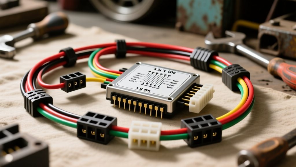
GMT330 Platform Electrical Architecture Overview
The 1998-2003 Chevrolet S10 (GMT330 platform) represents a transitional era in General Motors electrical engineering. Moving away from the simpler OBD-I and early OBD-II architectures, this generation introduced complex multiplexed-style sensor arrays, the Passlock II anti-theft system, and Central Sequential Fuel Injection (CSFI). When consulting an S10 wiring harness diagram for diagnostics, engine swaps, or custom harness fabrication, technicians must account for strict AWG (American Wire Gauge) requirements, specific GXL/TXL insulation standards, and highly localized ground networks. Failure to adhere to OEM pinout configurations or ignoring known harness degradation points—such as the steering column headlight circuit or the intake manifold bulkhead connector—will result in cascading electrical faults, limp-mode triggers, or complete no-start conditions.
4.3L V6 (L35) ECM Connector Pinout Reference
The Powertrain Control Module (PCM/ECM) for the 4.3L V6 utilizes a three-connector layout. Understanding the exact wire color codes and cavity numbers is critical when building an aftermarket adapter harness or diagnosing a no-start condition. The following data maps the primary sensor and power circuits based on OEM GM service documentation and the Haynes Chevrolet S10 Repair Manual.
C1 Connector (Blue) - Injector & Sensor Control
The C1 connector handles the high-speed switching of the CSFI injector sub-harness and critical 5V reference sensors. Wire gauge for injector control circuits is strictly 20 AWG to maintain rapid coil collapse times.
| Pin | Wire Color | Function | AWG |
|---|---|---|---|
| 01 | Dark Blue | Injector 1 Control | 20 |
| 02 | Dark Green/White | Injector 2 Control | 20 |
| 03 | Brown/White | Injector 3 Control | 20 |
| 04 | Light Blue/Black | Injector 4 Control | 20 |
| 05 | Yellow/Black | Injector 5 Control | 20 |
| 06 | Light Green/Black | Injector 6 Control | 20 |
| 33 | Dark Blue | TPS Signal (5V to 0.5V) | 20 |
| 34 | Dark Green | MAP Sensor Signal | 20 |
| 55 | Light Green/Black | Crankshaft Position Sensor (Low) | 20 |
| 56 | Yellow/Black | Crankshaft Position Sensor (High) | 20 |
C2 Connector (Red) - Power, Ground & Ignition
C2 is the lifeblood of the PCM, housing the main battery feeds, ignition-switched power, and the critical sensor ground returns. Voltage drop across these ground pins must not exceed 50mV under load.
| Pin | Wire Color | Function | AWG |
|---|---|---|---|
| 20 | Pink/Black | Battery Positive (Constant 12V) | 18 |
| 21 | Pink | Ignition Positive (Run/Start) | 18 |
| 58 | Black/White | PCM Logic Ground | 18 |
| 59 | Black/White | PCM Power Ground | 18 |
| 60 | Black/White | Sensor Return Ground | 18 |
| 68 | Tan/White | 4WD Low Range Signal | 20 |
CSFI Spider Injector Bulkhead Connector Diagnostics
One of the most notorious failure points referenced in any S10 wiring harness diagram for the 4.3L is the CSFI Spider injector sub-harness. Unlike traditional port injection, the S10 routes a 14-pin bulkhead connector through the upper intake manifold plenum. This connector is subjected to extreme heat cycling, crankcase oil vapors, and raw fuel exposure.
Failure Mode: Terminal fretting and micro-corrosion on cavities 1 through 6 (the injector control wires) cause intermittent open circuits. Because the PCM monitors coil flyback voltage, a poor connection will trigger a P0200-series code and cause a severe misfire.
Diagnostic Protocol:
- Disconnect the main harness bulkhead at the intake.
- Measure resistance across the injector coil pins. Specification is 11.5 to 12.5 ohms at 68°F (20°C).
- Perform a voltage drop test on the ground side of the injector circuit. A drop greater than 150mV during cranking indicates bulkhead terminal degradation.
- Repair: Do not use standard dielectric grease, which can trap moisture. Use a dedicated electrical contact cleaner followed by a thin application of Nyogel 760G or equivalent conductive grease. If pitting is visible on the male pins, the entire spider assembly and sub-harness must be replaced.
Headlight & Multifunction Switch Harness Melt
A critical design flaw in the GMT330 steering column harness involves the routing of high-amperage headlight circuits through the multifunction (dimmer) switch. The OEM harness utilizes 12 AWG wire for the headlight feeds, but the plastic connector cavity (C202) and the switch contacts cannot sustain the continuous thermal load of modern halogen or high-wattage bulbs.
Wire Identification:
- Yellow (12 AWG): Main feed from the headlight fuse.
- Tan (12 AWG): Low beam output to the headlights.
- Green (12 AWG): High beam output to the headlights.
- Brown (16 AWG): Parking light feed.
Engineering Solution: When rebuilding an S10 chassis harness, install a heavy-duty headlight relay bypass harness. Use 10 AWG primary wire (meeting SAE J1128 GXL standards) routed directly from the battery distribution block to two 40A Bosch-style relays mounted on the core support. Splice into the OEM Tan and Green wires using sealed butt connectors to provide a low-amp trigger signal (<50mA) to the relays, completely removing the high-current load from the steering column harness and multifunction switch.
Passlock II Anti-Theft Harness Diagnostics
The 1998-2003 S10 utilizes the Passlock II system, which integrates a Hall-effect sensor directly into the ignition lock cylinder housing. The sensor communicates with the Body Control Module (BCM) and PCM via a dedicated 3-wire harness.
| Wire Color | Function | Expected Voltage (Key OFF) | Expected Voltage (Key ON/RUN) |
|---|---|---|---|
| Red/White | 12V Reference Feed | 12.0V - 12.6V | 12.0V - 12.6V |
| Yellow | Passlock Signal | ~5.0V (Pull-up) | ~2.4V (Valid Code) |
| Black | Sensor Ground | < 0.05V Drop | < 0.05V Drop |
Troubleshooting the "Security" Light & No-Start:
If the Yellow signal wire suffers from a micro-break or high resistance (common where the harness flexes out of the steering column jacket), the BCM will not recognize the voltage drop, triggering a 10-minute security lockout. To diagnose, backprobe the Yellow wire at the ignition switch connector. Turn the key to the RUN position. If the voltage remains at 5.0V or drops to 0.0V, the internal Passlock sensor or the flexing harness pigtail has failed. Bypassing this requires either replacing the column harness pigtail or utilizing a dedicated Passlock II emulator module wired directly into the BCM communication bus.
Wire Gauge, Insulation, & Loom Repair Standards
When fabricating custom adapter harnesses for S10 engine swaps (such as adapting a 1998 4.3L harness to a standalone Holley Terminator X or Howell EFI system), adhering to automotive wire standards is non-negotiable. Standard PVC wire will melt against the exhaust manifolds and become brittle in sub-zero temperatures.
- Insulation Type: Always specify GXL (General Cross-Linked) or TXL (Thin-wall Cross-Linked) wire. These meet SAE J1128 specifications, offering a temperature rating up to 125°C (257°F) and superior resistance to under-hood chemicals.
- Wire Looming: Abandon cheap corrugated plastic split-loom for engine bay applications. Wrap the harness in Tesa 51036 PET fleece tape for high-temperature abrasion resistance, followed by a layer of Raychem DR-25 heat shrink tubing over all connector backshells to ensure a watertight seal.
- Connector Systems: For any harness extensions passing through the firewall or connecting to transmission solenoids, utilize Deutsch DT series or Weather-Pack connectors with silicone secondary locks to prevent terminal back-out during high-vibration off-road use.