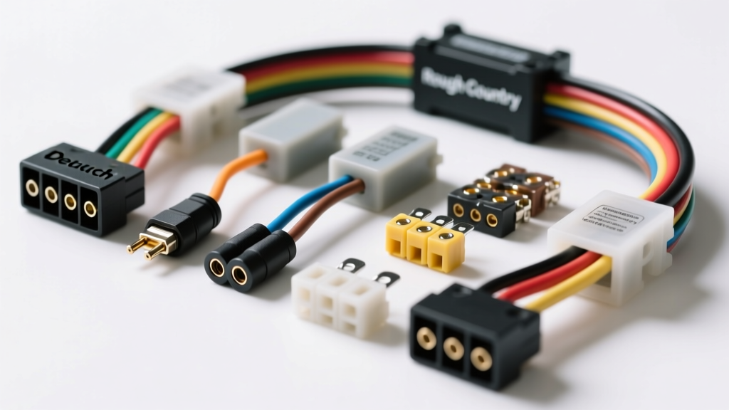
System Architecture Overview
Rough Country LED light bars, cubes, and chase lights rely on a standardized, relay-driven 12V DC wiring harness. While these kits are robust, the harsh environments of off-road use—combined with high-vibration chassis mounting—can lead to intermittent failures, flickering, or complete power loss. A standard Rough Country harness consists of a primary power feed (10 AWG), an ISO mini 4-pin relay, a 30A ATO blade fuse, a cabin-mounted trigger switch, and weather-sealed Deutsch DT-series connectors.
When diagnosing a failure, guessing leads to cut wires and ruined harnesses. This step-by-step troubleshooting flow isolates the fault using a systematic voltage-drop and continuity methodology, adhering to SAE J1128 primary cable standards and standard automotive electrical diagnostic practices.
Required Diagnostic Equipment
- Digital Multimeter (DMM): Must support DC Voltage (VDC), Resistance (Ohms), and Continuity.
- T-Pins or Back-Probes: For testing Deutsch connectors without piercing the wire insulation.
- Power Probe (Optional): For rapid 12V reference and ground verification.
- Dielectric Grease: For re-sealing weather-pack and Deutsch terminals.
Phase 1: Power Source and Fuse Verification
The most common point of failure in aftermarket lighting is the battery connection and primary fuse. Do not assume the fuse is good just by looking at it; internal micro-fractures can pass a visual inspection but fail under load.
- Measure Battery Resting Voltage: Place your DMM probes directly on the battery posts. You should read 12.4V to 12.6V. If below 12.0V, charge the battery before proceeding, as low voltage can prevent the relay coil from pulling in the armature.
- Inspect the Ring Terminal: Rough Country kits use a stamped or crimped ring terminal for the battery positive. Ensure the M8 or M10 bolt is torqued to the manufacturer's spec (typically 8-12 lb-ft) and free of corrosion.
- Test the 30A ATO Fuse: Pull the fuse and test for continuity across the blades. Alternatively, with the fuse installed, probe the exposed test slots on top of the blade fuse. Both sides must read full battery voltage (within 0.1V of the battery post reading).
Phase 2: The 4-Pin Relay Diagnostic Flow
The heart of the Rough Country harness is the standard ISO mini automotive relay. Understanding the pinout is critical. According to Littelfuse automotive relay specifications, the pins are numbered and function as follows:
| Pin Number | Wire Color (Typical RC) | AWG Size | Function & Circuit |
|---|---|---|---|
| 30 | Red | 10 AWG | Constant Battery Power (Input from Fuse) |
| 87 | Red / White Stripe | 10 AWG | Switched Power Output (To Light Bar) |
| 86 | White | 14 AWG | Trigger Power (From Dash Switch) |
| 85 | Black | 14 AWG | Relay Coil Ground (To Chassis) |
Testing the Relay Coil (Control Circuit)
Disconnect the relay from the harness socket. Set your DMM to Ohms (Resistance). Place probes on the socket terminals for Pin 85 and Pin 86. A healthy 12V relay coil will read between 60 and 120 Ohms. If it reads infinite (OL), the internal coil is burnt out. Replace the relay.
Testing the Relay Switch (Load Circuit)
Set your DMM to Continuity or Ohms. Probe the socket terminals for Pin 30 and Pin 87. With the relay unplugged, it should read infinite (OL). To test the mechanical action, use a fused jumper wire to apply 12V to Pin 86 and Ground to Pin 85 directly at the relay pins. You should hear an audible 'click', and the resistance between Pin 30 and 87 should drop to near 0.0 Ohms.
Phase 3: Switch and Trigger Circuit Testing
The Rough Country dash switch sends a low-current 12V signal to Pin 86 of the relay. If the switch fails, the relay never engages.
- Voltage Drop Test (Switch): Reconnect the relay. Turn the ignition to the ON/RUN position (if the switch is wired to an ignition source) or simply activate the switch. Back-probe the White wire at the relay socket (Pin 86). You should read full battery voltage.
- Ground Path Verification: The Black wire (Pin 85) must have a clean chassis ground. Paint, powder coating, and rust are insulators. If the relay clicks but the lights don't turn on, or if the relay gets excessively hot, measure the voltage drop between the relay ground pin and the negative battery post while the switch is ON. A reading above 0.1V indicates a high-resistance ground. Scrape the chassis to bare metal and apply dielectric grease.
Phase 4: Load Side and Deutsch Connector Inspection
Rough Country utilizes TE Connectivity Deutsch DT Series connectors for the final connection to the LED housing. These are environmentally sealed but are susceptible to mechanical and UV damage.
Symptom: Flickering or Intermittent Power
- Cause 1: Wedgelock Failure. The DT connector uses a plastic wedgelock to retain the metal pins. If the wedgelock was not fully seated during assembly, vibration can cause the pin to back out slightly, creating micro-arcing. Fix: Disconnect, inspect the orange or gray plastic wedgelock, push the pins fully forward, and snap the wedgelock into the secondary locking position.
- Cause 2: Silicone Boot Degradation. The rear silicone seal prevents water ingress. If torn, water enters the crimp barrel, causing green copper oxide corrosion. Fix: Cut back the wire, strip to bare copper, and re-crimp using a proper Deutsch DT crimp tool (do not use standard open-barrel crimpers, as they will crush the cylindrical DT pins and ruin the mating surface).
Symptom: Lights Do Not Turn On (Relay Clicks)
- Voltage Drop Test (Load Side): With the lights commanded ON, place the DMM positive probe on Pin 87 at the relay socket, and the negative probe on the positive pin of the Deutsch connector. A reading above 0.2V means there is high resistance in the 10 AWG Red/White wire (likely a damaged strand or corroded splice).
- Ground Side Check: The light bar itself must be grounded. Place the DMM positive probe on the negative pin of the Deutsch connector, and the negative probe on the bare chassis. Readings above 0.1V indicate the light bar's internal ground path or mounting bracket is compromised.
Symptom-Cause-Fix Decision Tree
| Observed Symptom | Probable Root Cause | Diagnostic Action & Fix |
|---|---|---|
| Relay clicks rapidly / Buzzing | Low voltage to relay coil or poor ground on Pin 85. | Check switch wiring for voltage drop. Clean chassis ground to bare metal. |
| Lights stay ON after switch is OFF | Relay contacts welded together due to inrush current spike. | Replace the ISO mini relay. Ensure LED driver is functioning correctly. |
| 30A Fuse blows immediately upon switching ON | Dead short on Pin 87 wire or internal LED driver failure. | Disconnect Deutsch connector. Test continuity from Pin 87 to Ground. If shorted, repair wire chafe. |
| Dash switch LED illuminates, but relay does not click | Switch LED is drawing current, but main trigger contact is burnt. | Bypass dash switch with a jumper wire. If relay clicks, replace the Rough Country switch assembly. |
| Lights are dim / Yellowish hue | Severe voltage drop on the 10 AWG power or ground wires. | Perform full circuit voltage drop test. Upgrade to 8 AWG if wire run exceeds 15 feet. |
Advanced Troubleshooting: CAN-Bus and BCM Interference
On modern vehicles (2015+ Jeep Wranglers, GM trucks, and Ford Raptors), the electrical system is monitored by the Body Control Module (BCM). If the Rough Country dash switch is wired directly into a factory lighting circuit (like the high-beam wire) to act as a trigger, the BCM may detect the parasitic draw of the relay coil (approx. 150mA) and interpret it as a short circuit. This will result in the factory headlights shutting off or throwing a dashboard CEL/cluster warning.
The Fix: Never splice the trigger wire directly into a factory headlight wire on a CAN-bus vehicle. Instead, use an automotive add-a-circuit fuse tap on a switched ignition fuse in the cabin fuse box to trigger Pin 86, ensuring the BCM remains entirely isolated from the aftermarket harness.