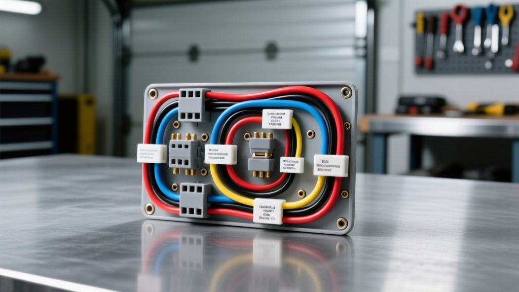
The Unique Abuse of the Door Jamb Environment
The drivers door wiring harness is arguably the most abused electrical conduit in any modern vehicle. Unlike the static harnesses routed through the vehicle's frame or under the dashboard, the door jamb harness operates in a dynamic flex zone. Every time you enter or exit the vehicle, the harness undergoes severe mechanical stress, bending, twisting, and temperature cycling. Over a vehicle's lifespan, this specific section of the harness will articulate tens of thousands of times. When repairing, replacing, or modifying this harness, standard automotive wiring practices are often insufficient—and sometimes outright dangerous. Below are the five most common mistakes technicians and DIYers make when working on a drivers door wiring harness, along with critical safety warnings to prevent electrical fires, module damage, and accidental airbag deployment.
Mistake #1: Using Standard PVC Wire Instead of TXL/GXL
The most frequent error in door jamb repair is pulling generic PVC-jacketed wire (like THHN or standard primary wire) through the rubber boot. Standard PVC becomes brittle in cold weather and lacks the mechanical memory to withstand continuous flexing. According to SAE Standard J1128, automotive primary cable must meet specific physical and electrical requirements for thin-wall and cross-linked insulations.
The Fix: You must use TXL (Thin-wall Cross-linked) or GXL (General Cross-linked) wire. As noted by Madsen Wire's automotive specifications, cross-linked polyethylene (XLPE) insulation offers superior resistance to abrasion, chemicals, and extreme temperatures (-51°C to 125°C). More importantly, XLPE jackets do not suffer from the cold-cracking and fatigue splitting that plague PVC in dynamic door hinge applications.
Mistake #2: Lethal Ignorance of Side-Impact Airbag Circuits
Modern vehicles route the side-impact (torso) and side-curtain airbag squib circuits directly through the drivers door wiring harness. These circuits are universally identified by yellow sheathing or yellow connector housings. A fatal mistake is probing these yellow wires with a standard digital multimeter (DMM) to check for continuity.
Safety Warning: A standard DMM outputs enough current during a resistance test to inadvertently trigger the airbag squib, causing a violent, face-level detonation. Furthermore, never use a 'test light' on these circuits. The National Highway Traffic Safety Administration (NHTSA) strictly warns against probing supplemental restraint system (SRS) wiring. Modern Yazaki and Delphi airbag connectors feature internal 'shorting bars' that safely bridge the squib pins when the connector is unplugged to prevent static discharge deployment. Always disconnect the vehicle battery, wait 15 minutes for the backup capacitors in the Sensing Diagnostic Module (SDM) to drain, and use a high-impedance breakout box if SRS circuit diagnosis is absolutely necessary.
Mistake #3: Guessing AWG Sizes and Overloading Terminals
Upgrading to aftermarket power window motors or adding high-draw accessory switches without calculating the amperage draw leads to melted Metri-Pack terminals and voltage drops. The drivers door harness carries a wide variance of current loads, and using an undersized wire for a high-draw component will cause the insulation to melt inside the confined space of the rubber door boot.
| Component | Typical AWG Size | Common OEM Wire Color | Terminal Type | Max Continuous Draw |
|---|---|---|---|---|
| Power Window Motor | 12 - 14 AWG | Dark Blue / Brown | Delphi Weather-Pack | 25A - 30A |
| Door Lock Actuator | 16 - 18 AWG | Tan / White | Metri-Pack 150 | 8A - 12A |
| Side Impact Sensor | 18 AWG | Yellow / Purple | SRS Sealed (Yellow) | < 1A (Signal) |
| CAN-Bus / Mirror | 20 - 22 AWG | Twisted Pair (Tan/Grn) | Metri-Pack 150 | < 2A (Data) |
| Speaker Outputs | 16 - 18 AWG | Gray / White / Green | Standard Spade / Molex | 10A - 15A |
The Fix: Always match the AWG to the circuit breaker or fuse rating protecting that specific module. If you are running a new 12 AWG power feed for an aftermarket window switch, ensure you are using the correct open-barrel crimp die for the larger terminal, and never force a 12 AWG wire into a terminal designed for 18 AWG.
Mistake #4: Soldering Splices in Dynamic Flex Zones
Many old-school mechanics believe that soldering a wire splice creates the most reliable connection. In a static engine bay harness, this is often true. In the drivers door wiring harness, soldering is a critical failure point. Solder wicks into the copper strands via capillary action, creating a rigid, stiff section of wire. As the door opens and closes, the flexing motion is transferred entirely to the boundary where the flexible copper meets the rigid solder joint. This causes rapid work hardening and eventual fatigue snapping of the copper strands.
The Fix: Use adhesive-lined (dual-wall) heat shrink crimp connectors or open-barrel terminal crimps. The mechanical crimp maintains the flexibility of the copper strands, while the inner meltable adhesive seal of the heat shrink prevents moisture intrusion and oxidation without creating a rigid fulcrum point.
Mistake #5: Mishandling the Weather Boot and BCM Intrusion
The rubber conduit (weather boot) connecting the A-pillar to the door is not just a physical shield; it is a critical waterproofing barrier. A common mistake is tearing this boot during harness removal or failing to seat it properly upon reinstallation. Worse, some technicians spray excessive amounts of silicone spray or liquid dielectric grease inside the boot to 'lubricate' the wires.
The Danger: If the A-pillar side of the boot seal fails, water enters the conduit. Through capillary wicking, water will travel along the outside of the wire insulation, bypassing the door cavity entirely, and flow directly into the Body Control Module (BCM) or Gateway Module located under the dashboard. This causes catastrophic, multi-thousand-dollar module corrosion. Furthermore, liquid dielectric grease can trap existing moisture inside the connector housing and degrade certain plastic terminal retainers over time.
The Fix: Inspect the rubber boot for micro-tears. If damaged, replace the entire grommet. Use only a light application of NYE synthetic dielectric grease (like Nye 812A) applied directly to the metal terminal mating surfaces, not slathered inside the rubber boot.
Diagnostic Decision Tree: Troubleshooting Intermittent Door Faults
When dealing with intermittent electrical gremlins (e.g., window works only when the door is slammed, or dome lights flicker when turning the steering wheel), use this structured diagnostic approach to isolate the drivers door wiring harness fault:
- Symptom: Power window operates slowly or stops mid-travel, but works when pushing on the door panel.
Cause: Voltage drop due to frayed 12 AWG ground or power wire inside the jamb boot.
Action: Perform a loaded voltage drop test across the jamb harness while actuating the window. A drop greater than 0.2V indicates internal strand breakage. - Symptom: 'Service Airbag' light illuminates only when the door is opened or closed.
Cause: Micro-fracture in the 18 AWG yellow SRS wire or a backed-out terminal in the yellow door-side connector.
Action: Visually inspect the yellow wires for jacket stress marks. Check the terminal retention tab (lance) inside the connector housing using a plastic pick. Never use a metal probe. - Symptom: CAN-Bus communication codes (U-codes) for the Door Module (DDM) set when driving over bumps.
Cause: Twisted pair (CAN-High / CAN-Low) has separated or shorted to ground due to insulation wear against the metal door hinge bracket.
Action: Measure the resistance across the CAN-High and CAN-Low pins at the DDM connector (should be ~60 ohms). If infinite or erratic while wiggling the boot, the twisted pair is compromised and must be replaced with properly twisted 22 AWG automotive data wire.
Summary
Working on a drivers door wiring harness requires an understanding of dynamic mechanical stress, material science, and strict safety protocols regarding SRS systems. By selecting the correct TXL wiring, avoiding solder in flex zones, respecting airbag circuits, and maintaining the integrity of the weather seals, you ensure long-term reliability and safety for the vehicle's occupants and electrical modules.