Epsilon Platform Electrical Architecture & The GMLAN Bus
The 2012 Chevrolet Malibu represents the final model year of the seventh-generation Epsilon platform. From an automotive electrical perspective, this vehicle marks a definitive shift away from traditional hardwired 12V switched ignition circuits in favor of multiplexed data networks. The factory infotainment system does not receive a standard 12V accessory wake-up signal from the ignition cylinder. Instead, it relies on the Body Control Module (BCM) and the General Motors Local Area Network (GMLAN) to dictate power states, Retained Accessory Power (RAP) logic, and chime routing.
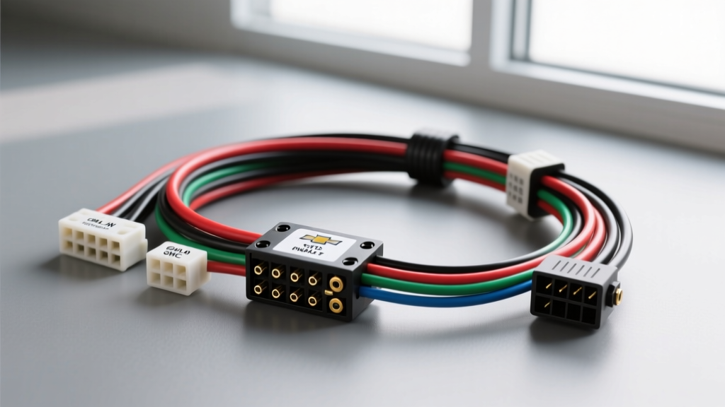
When replacing the OEM head unit with an aftermarket receiver, understanding the 2012 Chevy Malibu radio wiring harness is critical. Tapping into the fuse box or ignition switch for a switched 12V source can backfeed the BCM, trigger U-codes (network communication faults), and cause severe parasitic battery draws. This advanced technical deep dive covers the exact Delphi connector pinouts, GMLAN integration protocols, and premium audio bypass procedures required for a flawless installation.
OEM Connector Identification & Pinout Matrix
The base audio system in the 2012 Malibu utilizes two primary Delphi GT-series connectors at the rear of the head unit: a 24-pin main harness (X1) for power, ground, and data, and an 8-pin harness (X2) for speaker outputs. The terminals are predominantly GT 150 (1.5mm) for signals and GT 280 (2.8mm) for power and ground circuits.
24-Pin Main Harness (X1) Breakdown
The X1 connector manages constant power, ground, illumination, and the vital GMLAN serial data bus. Wire gauges range from 18 AWG for low-current signals to 14 AWG for primary power delivery.
| Pin | Wire Color | Function | AWG |
|---|---|---|---|
| 1 | Orange/Black | Instrument Panel Illumination / Dimmer | 18 |
| 2 | Yellow | Battery 12V+ Constant (B+) | 14 |
| 8 | Brown/White | Park Lamp Circuit | 18 |
| 9 | Black/White | Primary Ground (GND) | 14 |
| 11 | GMLAN Serial Data | Single Wire CAN (SWCAN) Bus | 18 |
| 12 | Shield/Drain | Data Bus Shield (if equipped) | 20 |
| 16 | Dark Green/White | Vehicle Speed Sensor (VSS) Signal | 18 |
8-Pin Audio Output Harness (X2) Breakdown
The X2 connector carries the amplified speaker-level signals for the base 4-speaker or 6-speaker configurations. All speaker wires are 18 AWG. Note that GM standard color coding relies on specific stripe patterns to denote polarity.
| Pin | Wire Color | Speaker Location & Polarity |
|---|---|---|
| 1 | Tan | Left Front (+) |
| 2 | Gray | Left Front (-) |
| 3 | Light Green | Right Front (+) |
| 4 | Dark Green | Right Front (-) |
| 5 | Brown | Left Rear (+) |
| 6 | Yellow | Left Rear (-) |
| 7 | Dark Blue | Right Rear (+) |
| 8 | Light Blue | Right Rear (-) |
Retained Accessory Power (RAP) & Ignition Wake-Up Protocols
The most common point of failure in 2012 Malibu aftermarket installations is the lack of a traditional 12V accessory (red) wire. The BCM retains power to the radio circuit until the driver's door is opened or a 10-minute timeout expires. This is known as Retained Accessory Power (RAP).
To properly integrate an aftermarket radio, you must use a GMLAN data bus interface module (such as the Axxess GMOS-LAN-04 or Metra AFDI-5V). These modules intercept the GMLAN serial data packets on Pin 11 of the X1 connector. When the BCM broadcasts the 'Ignition Run' or 'RAP Active' CAN message, the interface module triggers an internal relay, providing a clean, fused 12V switched output to the aftermarket radio's red accessory wire. Attempting to hardwire the radio's accessory lead to the ignition cylinder bypasses the BCM's sleep logic and will result in a parasitic draw that can drain the battery overnight.
Steering Wheel Controls (SWC) & OnStar Audio Retention
The 2012 Malibu utilizes a resistive ladder network for the physical steering wheel control buttons, but those signals are first read by the BCM, digitized, and transmitted over the GMLAN bus to the factory radio. Furthermore, OnStar turn-by-turn navigation prompts and Bluetooth phone audio are injected directly into the audio stream via the data bus.
To retain these features, a dual-purpose digital interface (like the PAC RP5-GM11) is required. This module acts as a gateway, translating GMLAN OnStar audio packets into standard RCA pre-outs, and simultaneously reading the BCM's SWC data packets to output the equivalent resistive or IR signals required by aftermarket head units (e.g., Pioneer, Kenwood, Alpine). Failure to use a Class 2/GMLAN retention module will result in the permanent loss of OnStar audio and steering wheel functionality.
Premium Audio (Uplevel) Amplifier Bypass Procedures
If your 2012 Malibu is equipped with the premium 7-speaker system, the 8-pin X2 connector at the radio does not carry standard speaker-level outputs. Instead, it carries low-level differential signals (or line-level data) routed to a factory amplifier located in the trunk, behind the rear passenger side paneling.
Bypass Protocol:
- Disconnect the Battery: Isolate the negative terminal to prevent shorting the BCM data lines.
- Access the Trunk Amplifier: Remove the trunk pass-through trim and unbolt the factory amp.
- Abandon Factory Wiring: The factory speaker harness uses 20 AWG wire, which is insufficient for aftermarket head unit power (minimum 16 AWG OFC recommended). Unplug the amp and tape off the factory connectors.
- Run New Speaker Wire: Route four pairs of 16 AWG Oxygen-Free Copper (OFC) speaker wire from the dash, down the driver-side kick panel, under the carpet, and through the factory rubber trunk grommet.
- Solder and Seal: Use Mil-Spec adhesive-lined heat shrink at all splice points in the dash to prevent oxidation and voltage drop over time.
Advanced Troubleshooting & Parasitic Draw Diagnostics
When diagnosing electrical faults post-installation, utilize a digital multimeter (DMM) capable of reading CAN bus voltage fluctuations and a low-amp clamp meter for parasitic draw testing.
- Symptom: Battery drains 0.5A+ overnight after radio swap.
Cause: The aftermarket radio or an improperly wired data interface is keeping the GMLAN bus 'awake', preventing the BCM from entering Sleep Mode.
Fix: Verify the data interface module supports 'Sleep Mode Logic'. Ensure the radio's accessory wire is not backfeeding voltage into the BCM's ignition sense circuits. - Symptom: Turn signal chimes and seatbelt warnings are missing.
Cause: In the 2012 Malibu, the BCM generates chime data and sends it to the radio, which plays the sound through the Left Front speaker. Bypassing the data bus severs this link.
Fix: Install a chime retention module (e.g., GMOS-01) that features a dedicated piezoelectric or localized speaker to generate safety chimes independently of the audio system. - Symptom: Illumination dimmer circuit blows the radio fuse.
Cause: The Orange/Black dimmer wire on Pin 1 carries a PWM (Pulse Width Modulated) signal from the BCM, not a simple 12V analog voltage. Connecting this directly to an aftermarket radio's 'Illumination' input can short the BCM driver.
Fix: Leave the PWM dimmer wire disconnected, or use a PWM-to-Analog 12V step-down converter if variable dash dimming is strictly required.
Authoritative References
For further engineering specifications and OEM wiring schematics, consult the following authoritative automotive electrical resources:
- Helm Incorporated (Official GM Service Manuals) - Publisher of the factory Epsilon platform electrical diagnostic manuals and GMLAN network topology charts.
- SAE International (J1939 & CAN Standards) - Technical documentation on Controller Area Network (CAN) and Single Wire CAN (SWCAN) physical layer requirements.
- Metra Electronics Technical Bulletins - Application-specific integration guides for GM Epsilon II data bus retention and RAP logic interfaces.