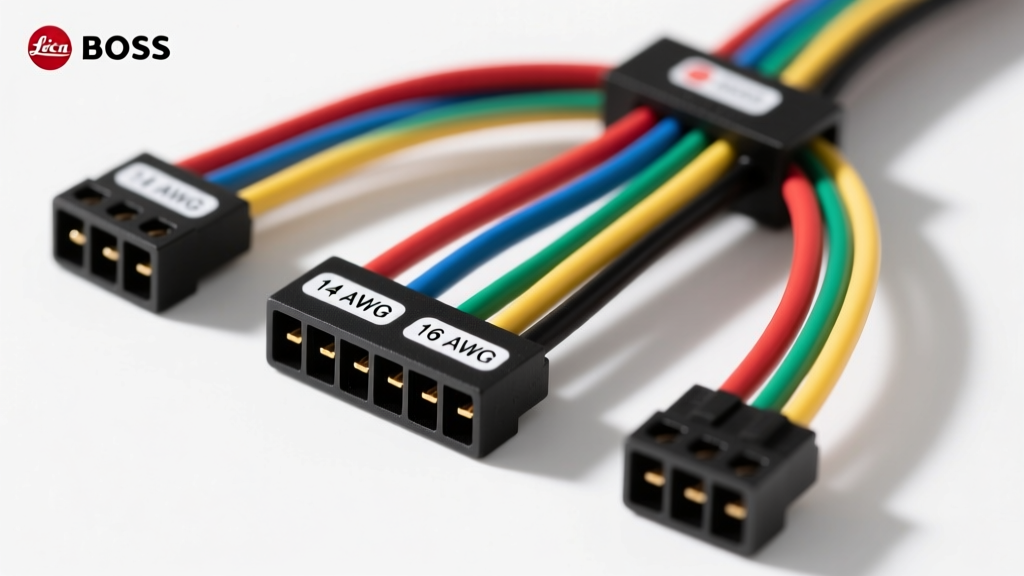
Boss RT3 Wiring Harness System Overview
The Boss RT3 (RTIII) snow plow electrical system represents a significant evolution in commercial and municipal snow removal technology. Unlike older relay-based straight-blade systems, the RT3 platform integrates advanced hydraulic controls, multiplex communication modules, and high-amperage solenoid packs. Understanding the specific architecture of the Boss RT3 wiring harness is critical for installation, maintenance, and diagnosing intermittent electrical faults. This technical specification reference details the pin configurations, wire gauge requirements, and diagnostic procedures for both standard and multiplex RT3 harness variants.
According to the official Boss Snowplows technical documentation, the RT3 system relies on a robust vehicle-side harness that interfaces with the plow-side harness via a heavy-duty, weather-sealed connector. Proper torque specifications, dielectric grease application, and adherence to SAE wiring standards are mandatory to prevent voltage drop and premature connector failure in harsh, high-salt environments.
Connector Configurations: 11-Pin vs. 13-Pin
The Boss RT3 wiring harness primarily utilizes two connector configurations depending on the model year and whether the system employs a standard relay setup or a modern multiplex control module. Identifying your connector type is the first step in any diagnostic procedure.
Standard 11-Pin RT3 Connector Pinout
The 11-pin connector is standard on earlier RT3 models and non-multiplex vehicle harnesses. It consolidates lighting, main power, and hydraulic trigger signals into a single die-cast or heavy-duty thermoplastic housing.
| Pin | Wire Color | Function | AWG | Circuit Type |
|---|---|---|---|---|
| 1 | Black | Main System Ground | 10 | Ground |
| 2 | Brown | Tail / Marker Lights | 16 | Lighting |
| 3 | Yellow | Left Turn / Brake | 16 | Lighting |
| 4 | Green | Right Turn / Brake | 16 | Lighting |
| 5 | Red | 12V+ Battery Feed (Fused) | 10 (or 8) | Power |
| 6 | White | Lighting Common Ground | 14 | Ground |
| 7 | Blue | Headlight High Beam | 16 | Lighting |
| 8 | Purple | Headlight Low Beam | 16 | Lighting |
| 9 | Orange | Lift / Down Solenoid Trigger | 14 | Signal |
| 10 | Dark Green | Angle Left Solenoid Trigger | 14 | Signal |
| 11 | Light Green | Angle Right Solenoid Trigger | 14 | Signal |
Multiplex 13-Pin RT3 Connector Pinout
Newer RT3 systems utilize a 13-pin connector to accommodate multiplex data lines. The multiplex module translates digital cab control inputs into specific solenoid triggers, reducing the number of high-current wires passing through the firewall.
| Pin | Wire Color | Function | AWG | Circuit Type |
|---|---|---|---|---|
| 1 | Black | Main System Ground | 10 | Ground |
| 2 | Brown | Tail / Marker Lights | 16 | Lighting |
| 3 | Yellow | Left Turn / Brake | 16 | Lighting |
| 4 | Green | Right Turn / Brake | 16 | Lighting |
| 5 | Red | 12V+ Battery Feed (Fused) | 10 | Power |
| 6 | White | Lighting Common Ground | 14 | Ground |
| 7 | Blue | Headlight High Beam | 16 | Lighting |
| 8 | Purple | Headlight Low Beam | 16 | Lighting |
| 9 | Black/White | Multiplex Data Line (CAN Low) | 18 | Data |
| 10 | Black/Green | Multiplex Data Line (CAN High) | 18 | Data |
| 11 | Orange | Lift / Down Solenoid Trigger | 14 | Signal |
| 12 | Dark Green | Angle Left Solenoid Trigger | 14 | Signal |
| 13 | Light Green | Angle Right Solenoid Trigger | 14 | Signal |
Wire Gauge and Routing Specifications
Adherence to SAE J1128 standards for low-tension primary cable is critical for the Boss RT3 wiring harness. The main power feed (Pin 5) and main ground (Pin 1) must utilize a minimum of 10 AWG cross-linked polyethylene (XLPE) wire. For vehicles with extended wheelbases or long-bed configurations where the battery is located more than 10 feet from the plow solenoid, upgrading the main power and ground circuits to 8 AWG is highly recommended to mitigate voltage drop.
All wiring routed through the engine bay must be encased in split corrugated loom or wrapped in high-temperature Tesa cloth tape to protect against abrasion and radiant heat from exhaust manifolds. Firewall pass-throughs must utilize OEM-style rubber grommets; drilling a bare hole through the firewall and pulling the RT3 cab control harness will inevitably lead to short circuits against the sheet metal within the first season of operation.
Solenoid and Relay Pack Wiring Reference
The RT3 system typically employs a continuous-duty Trombetta or White-Rodgers solenoid to engage the main hydraulic motor. When diagnosing a 'no-power' condition at the plow motor, technicians must verify both the high-amperage load circuit and the low-amperage coil trigger circuit.
- Coil Resistance: A healthy RT3 solenoid coil should read between 12 and 15 ohms across the small trigger terminals. An infinite reading indicates an open internal coil winding.
- Trigger Voltage: When the cab control is activated, the trigger terminal should receive a minimum of 10.5V. If voltage is below 10V, inspect the 14 AWG trigger wires in the main harness for corrosion or broken strands.
- Load Side Voltage Drop: With the solenoid engaged and the motor under load, measure the voltage drop across the solenoid's large terminals. A voltage drop exceeding 0.5V indicates pitted internal contacts, requiring immediate solenoid replacement.
Common RT3 Harness Failure Modes and Diagnostics
Snow plow electrical systems operate in the most hostile environments in the automotive sector. The combination of road salt, extreme thermal cycling, and high-pressure washes creates specific failure modes unique to the RT3 harness.
1. Connector Pin Corrosion and Fretting
The 11-pin and 13-pin connectors are sealed with silicone O-rings, but these seals degrade over time. Moisture ingress leads to galvanic corrosion on the brass pins. Fix: Disconnect the harness, clean pins with electrical contact cleaner and a nylon brush, and apply a generous coat of dielectric tune-up grease before reconnecting. Never use petroleum-based grease, which swells the silicone seals.
2. Multiplex Module CAN-Bus Errors
On 13-pin multiplex systems, a damaged CAN High or CAN Low wire (Pins 9 and 10) will cause the plow to become entirely unresponsive, often accompanied by a flashing red LED on the cab control. Diagnostic: Use an oscilloscope to verify the CAN signal. CAN High should idle around 2.5V and peak at 3.5V, while CAN Low should idle at 2.5V and drop to 1.5V during data transmission. A flatline indicates a severed data wire or a shorted multiplex module.
3. Intermittent Lighting Grounds
If the plow marker lights flicker or the turn signals hyper-flash, the issue is rarely the bulb. It is almost always a voltage drop on the 14 AWG White lighting ground wire (Pin 6). Diagnostic: Perform a voltage drop test between the plow light housing and the vehicle battery negative terminal while the lights are active. Any reading over 0.2V requires repairing the ground circuit or adding a secondary 12 AWG ground strap directly from the plow frame to the vehicle chassis, as recommended by National Truck Equipment Association (NTEA) guidelines for upfit electrical systems.
Maintenance Best Practices
To ensure the longevity of your Boss RT3 wiring harness, implement a pre-season and mid-season inspection protocol. Verify the 150A or 200A Mega fuse located on the main power feed for signs of thermal stress or micro-cracking in the fuse element. Inspect the harness where it rests against the truck's front bumper or grille supports, adding additional split-loom protection if the factory abrasion guards have worn through. Proper maintenance of the RT3 harness ensures reliable hydraulic response and legal lighting compliance throughout the winter season.