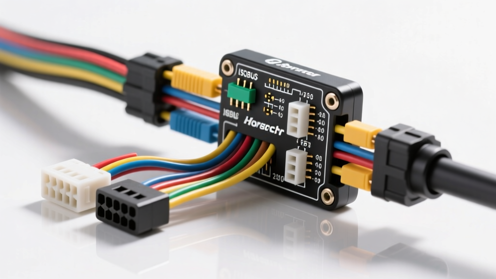
Overview of Horsch Sprinter Electrical Architecture
When integrating precision agriculture implements with modern high-horsepower tractors, the Horsch Sprinter wiring harness tractor connection serves as the critical data and power backbone. Unlike older mechanical seed drills that relied solely on simple lighting circuits, modern Horsch Sprinter models utilize complex ISOBUS (ISO 11783) protocols for variable rate seeding, GPS-based section control, and real-time optical seed monitoring. Understanding the exact pin configurations, wire gauges, connector types, and diagnostic parameters of the Horsch Sprinter wiring harness tractor interface is essential for agricultural technicians diagnosing communication faults, replacing damaged umbilical cables, or retrofitting older tractors with modern Ag electronics. This technical specification reference details the exact electrical architecture required to maintain optimal continuity and data throughput between the tractor and the Horsch Sprinter implement.
ISOBUS (ISO 11783) Main Implement Connector (MIC) Pinout
The primary connection point for the Horsch Sprinter wiring harness tractor interface is the Main Implement Connector (MIC). Modern Sprinter models utilize the standardized 9-pin ISOBUS circular connector, conforming strictly to ISO 11783-2 specifications. This heavy-duty connector handles both the high-current power requirements for the implement's primary ECU and the high-speed CAN bus data lines (ISO 11783-3) that communicate with the tractor’s Universal Terminal (UT). The CAN bus operates at 250 kbps and requires a twisted pair configuration to reject electromagnetic interference (EMI) generated by the tractor's alternator and PWM hydraulic solenoids.
| Pin | Function | Wire Color (ISO) | Wire Size (mm² / AWG) | Technical Notes |
|---|---|---|---|---|
| A | Shield / Drain | Bare / Green | 1.5 mm² / 16 AWG | Must be grounded at the tractor ECU only to prevent ground loops. |
| B | CAN_L (Low) | Yellow | 0.5 mm² / 20 AWG | Twisted pair with Pin C. Nominal voltage 2.5V (recessive). |
| C | CAN_H (High) | Green | 0.5 mm² / 20 AWG | Twisted pair with Pin B. Nominal voltage 2.5V (recessive). |
| D | Switched Power | Red | 4.0 mm² / 12 AWG | Ignition-switched 12V. Max continuous draw 15A. |
| E | Ground | Black | 4.0 mm² / 12 AWG | Main implement ground return. Must have <0.2V drop under load. |
| F | Battery Power | White | 4.0 mm² / 12 AWG | Constant 12V for ECU memory and keep-alive circuits. |
| G | Analog Aux 1 | Brown | 1.5 mm² / 16 AWG | Reserved for auxiliary analog sensors (e.g., hitch draft). |
| H | Analog Aux 2 | Blue | 1.5 mm² / 16 AWG | Reserved for auxiliary analog sensors. |
| I | Reserved | N/A | N/A | Not currently utilized in standard Sprinter configurations. |
Standard 7-Pin DIN Lighting and Auxiliary Harness
While the ISOBUS connector handles data and ECU power, the Horsch Sprinter wiring harness tractor setup also branches into a standard 7-pin DIN connector (ISO 1724) to manage road lighting, turn signals, and brake lights. This legacy circuit is entirely separate from the CAN bus network and is powered directly by the tractor's lighting control module. Voltage drop on these circuits is a common failure point, especially when aftermarket LED lighting kits are installed on the Sprinter without updating the tractor's flasher relays or pulse-width modulation (PWM) lighting controllers.
| Pin | Function | Wire Color (DIN) | Wire Size |
|---|---|---|---|
| 1 | Left Turn Signal | Yellow | 1.5 mm² / 16 AWG |
| 2 | Rear Fog Light | Blue | 1.5 mm² / 16 AWG |
| 3 | Ground (Lighting) | White | 2.5 mm² / 14 AWG |
| 4 | Right Turn Signal | Green | 1.5 mm² / 16 AWG |
| 5 | Tail / Marker Lights | Brown | 1.5 mm² / 16 AWG |
| 6 | Stop / Brake Lights | Red | 1.5 mm² / 16 AWG |
| 7 | Reverse / Aux 12V | Black | 1.5 mm² / 16 AWG |
Sub-Harness Specifications: Metering Drives and Seed Sensors
The internal routing of the Horsch Sprinter wiring harness relies on modular sub-harnesses connected via weather-sealed Deutsch DT and DTM series connectors. These sub-harnesses distribute power and data to the individual row units, metering drives, and optical seed sensors. Because these harnesses are subjected to extreme vibration, dust ingress, and chemical exposure from seed treatments, proper pin crimping and seal insertion are critical.
Optical Seed Sensor Wiring (Deutsch DTM 4-Pin)
Each row unit on the Sprinter features an optical seed sensor to monitor population and singulation. These sensors utilize a 4-pin Deutsch DTM connector. The wiring specification is as follows:
- Pin 1 (Red): 5V Excitation (Supplied by the Sprinter Master ECU). Wire: 0.35 mm² (22 AWG).
- Pin 2 (White): Signal Return (Pulse output). Wire: 0.35 mm² (22 AWG).
- Pin 3 (Black): Sensor Ground. Wire: 0.35 mm² (22 AWG).
- Pin 4 (Bare/Shield): Drain wire for EMI protection. Must be terminated at the ECU shield bus.
PWM Hydraulic Valve Control (Deutsch DT 6-Pin)
For Sprinter models utilizing hydraulic variable-rate metering drives, the main ECU sends a PWM signal to the hydraulic proportional valves. The 6-pin Deutsch DT connector handles the high-current solenoid loads:
- Pins 1 & 2: Solenoid Coil Power (12V PWM). Wire: 2.0 mm² (14 AWG).
- Pins 3 & 4: Solenoid Coil Ground. Wire: 2.0 mm² (14 AWG).
- Pins 5 & 6: Spool Position Feedback (LVDT sensor). Wire: 0.5 mm² (20 AWG).
Environmental Sealing, Torque Specs, and Maintenance
Agricultural environments are notoriously harsh on electrical connections. The Horsch Sprinter wiring harness tractor interface requires strict adherence to environmental sealing protocols. All Deutsch DT and DTM connectors must utilize the appropriate silicone wedge locks and secondary wire seals. When mating the main ISOBUS 9-pin circular connector, the threaded locknut must be torqued to exactly 4.5 Nm to 6.0 Nm (40-53 in-lbs). Under-torquing allows moisture ingress leading to galvanic corrosion on the brass pins, while over-torquing can crack the thermoplastic connector housing or strip the threads on the tractor's bulkhead receptacle. Always apply a light coat of dielectric grease (such as Nyogel 760G) to the ISOBUS pins before mating to prevent oxidation and ensure optimal conductivity.
Diagnostic Troubleshooting Decision Tree
When diagnosing faults in the Horsch Sprinter wiring harness tractor connection, technicians should follow this systematic decision tree to isolate CAN bus and power faults:
- Symptom: Tractor UT displays 'Implement Not Connected' or 'ISOBUS Timeout'.
- Step 1: Verify Pin F (Battery) and Pin E (Ground) at the implement side of the MIC. Voltage must read >12.4V with the tractor off, and >13.8V with the tractor running. If voltage is low, check the tractor's ISOBUS fuse block and clean the Pin E ground lug on the tractor chassis.
- Step 2: Measure CAN bus termination resistance. Disconnect the tractor battery and the implement MIC. Using a multimeter, measure resistance between Pin B (CAN_L) and Pin C (CAN_H) on the implement harness. The reading must be exactly 120 ohms (indicating the implement's internal terminating resistor is intact). If the reading is infinite (OL), the internal ECU resistor is blown or the harness is severed. If the reading is near 0 ohms, there is a short between the CAN lines.
- Step 3: Check for CAN bus voltage bias. Reconnect the MIC and turn the tractor ignition ON (do not start engine). Measure DC voltage from Pin E (Ground) to Pin B (CAN_L). It should read approximately 2.5V. Measure Pin E to Pin C (CAN_H). It should also read approximately 2.5V. If both read 0V or 12V, the tractor's CAN bus transceiver has failed or there is a dead short to ground/power in the umbilical cable.
- Symptom: Optical Seed Sensors Show 'No Signal' on UT.
- Step 1: Check the 5V excitation circuit at the Master ECU. If the 5V reference is missing, the ECU may have entered protection mode due to a shorted sensor wire rubbing against the seed tube.
- Step 2: Inspect the Deutsch DTM wedge locks. Vibration from the Sprinter's opener discs frequently causes improper crimps to back out of the connector cavity if the secondary wedge lock was not fully seated during assembly.
Authoritative References
For further engineering details on agricultural implement wiring, technicians should consult the following authoritative standards and manufacturer documentation:
- ISOBUS.net (ISO 11783 Standard Reference) - The definitive global resource for ISOBUS compatibility, connector pinouts, and Conformance Testing guidelines.
- SAE J1939 High-Speed CAN for Vehicle Control and Communications - The foundational protocol upon which the ISO 11783 agricultural CAN bus layer is built, detailing physical layer requirements and message formatting.
- American Society of Agricultural and Biological Engineers (ASABE) - Refer to ANSI/ASABE S570 for standardized lighting and signaling wiring practices for agricultural equipment.