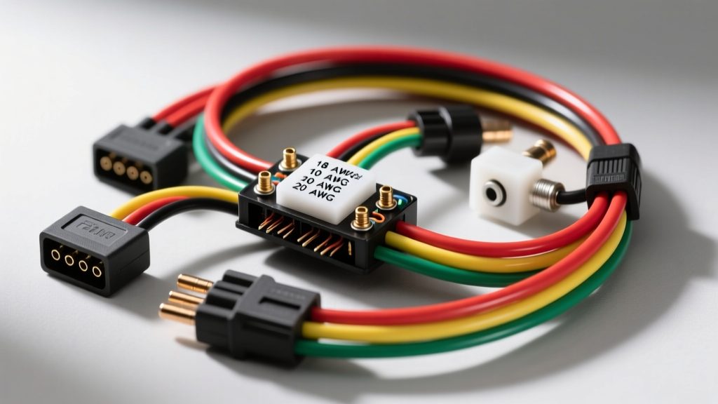
Introduction to Electronic Throttle Control Harnesses
The transition from mechanical cables to Drive-by-Wire (DBW) systems fundamentally changed how engines manage air intake. At the heart of this system is the electronic throttle body (ETB), and connecting it to the Powertrain Control Module (PCM) is a highly specialized throttle body wiring harness. Unlike older single-wire idle air control setups, modern DBW harnesses must carry high-current motor control signals alongside ultra-sensitive, low-voltage sensor data. For beginners and seasoned technicians alike, understanding the architecture of this harness is critical for diagnosing limp-mode conditions, clearing persistent P0120 or P0220 diagnostic trouble codes (DTCs), and performing reliable pigtail repairs.
This guide breaks down the fundamental wiring principles of the industry-standard 6-pin electronic throttle body connector, detailing wire gauges, terminal specifications, and multimeter diagnostic procedures to ensure your engine swap or repair is executed flawlessly.
The Anatomy of a 6-Pin DBW Throttle Body Connector
Most modern domestic and import vehicles utilize a 6-way USCAR-compliant weather-sealed connector for the electronic throttle body. This harness must manage two distinct electrical sub-systems within a single housing: the Throttle Actuator Motor (TAM) and the dual-redundant Throttle Position Sensors (TPS).
Why Dual Potentiometers?
To meet strict ISO 26262 functional safety standards, the PCM requires redundant position feedback. The harness carries signals for TPS 1 and TPS 2. These two internal potentiometers are wired inversely. As the throttle blade opens, TPS 1 voltage increases (e.g., from 0.5V to 4.5V), while TPS 2 voltage decreases (e.g., from 4.5V to 0.5V). The PCM continuously adds these two values together; if the sum deviates from exactly 5.0 Volts by more than a few millivolts, the PCM assumes a harness fault or sensor failure and immediately cuts power to the throttle motor, triggering a fail-safe limp mode.
Standard 6-Pin ETB Pinout and Wire Specifications
While specific wire colors vary by OEM (General Motors, Ford, Toyota, etc.), the circuit architecture and American Wire Gauge (AWG) requirements remain remarkably consistent. Below is the reference architecture for a standard Delphi/Bosch-style 6-pin DBW harness.
| Pin | Circuit Function | Typical Wire Color (GM/Ford) | AWG | Circuit Type |
|---|---|---|---|---|
| 1 | Throttle Actuator Motor (+) | Grey / Dark Blue | 18 AWG | High-Current PWM |
| 2 | Throttle Actuator Motor (-) | Black / Dark Green | 18 AWG | High-Current PWM |
| 3 | 5-Volt Reference (VREF) | Red / Pink | 20 AWG | Low-Current Analog |
| 4 | TPS 1 Signal | Light Blue / White | 22 AWG | Low-Current Analog |
| 5 | TPS 2 Signal | Yellow / Orange | 22 AWG | Low-Current Analog |
| 6 | Low Reference (Sensor Ground) | Black/White Tracer | 20 AWG | Low-Current Ground |
Note: Always consult your specific vehicle's factory service manual for exact color codes, as harness revisions occur mid-production.
Understanding Wire Gauge and USCAR Terminal Standards
A common beginner mistake is using uniform wire sizing when fabricating a custom engine swap harness or repairing a damaged pigtail. The Molex USCAR-21 specifications dictate strict terminal retention and wire gauge mating requirements.
- Motor Circuits (Pins 1 & 2): These circuits require 18 AWG wire. The PCM uses Pulse Width Modulation (PWM) to drive the DC motor. Breaking the throttle blade's initial static friction (stiction) requires a brief surge of up to 8-12 amps. Using 20 or 22 AWG wire here will cause excessive voltage drop, resulting in sluggish throttle response or P0121 (Throttle/Pedal Position Sensor/Switch 'A' Circuit Range/Performance) codes.
- Sensor Circuits (Pins 3, 4, 5, 6): These carry less than 50 milliamps and utilize 20 or 22 AWG wire. Using wire that is too thick will prevent the terminal from seating properly into the connector housing, leading to terminal back-out and intermittent signal loss.
Step-by-Step Pigtail Harness Replacement
Heat and vibration often cause the wire insulation near the throttle body connector to crack, leading to moisture ingress and copper corrosion. When replacing a pigtail harness, proper crimping is non-negotiable. Soldering is strictly prohibited in modern automotive harnesses due to the creation of a rigid stress point that will eventually snap under engine vibration.
The Correct Crimping Procedure
- Strip the Wire: Use a precision wire stripper to remove exactly 3mm to 4mm of insulation. Do not nick the copper strands.
- Position the Terminal: Use a ratcheting automotive crimping tool (such as the Delphi or TE Connectivity ratcheting crimpers). Place the open-barrel terminal in the tool.
- Conductor Crimp: The inner 'U' shaped tabs must bite into the bare copper strands, creating a cold-weld gas-tight seal.
- Insulation Crimp: The outer, larger tabs must wrap tightly around the wire's PVC or XLPE insulation to provide strain relief.
- Weather Seal Installation: Slide the silicone ribbed weather seal over the wire before crimping. The seal must sit flush against the terminal shoulder.
- Terminal Insertion: Push the terminal into the plastic housing until you hear and feel a distinct 'click'. Perform the 'push-pull' test by gently tugging the wire backward to ensure the locking tang is engaged.
Multimeter Diagnostics: Testing the Redundant Potentiometers
When diagnosing a throttle body wiring harness, you must isolate whether the fault lies in the motor control side or the sensor feedback side. Always begin diagnostics with the Key On, Engine Off (KOEO) and the connector plugged in using a T-pin or back-probe tool to avoid spreading the female terminals.
Symptom-Cause-Fix Decision Tree
- Symptom: TPS 1 reads 0.0V and TPS 2 reads 5.0V constantly.
Cause: Open circuit on Pin 6 (Low Reference Ground) or Pin 3 (5V VREF).
Fix: Perform a voltage drop test on Pin 6 back to the PCM. If voltage drop exceeds 0.1V, repair the ground wire. - Symptom: Codes P0120 and P0220 set simultaneously, engine in limp mode.
Cause: Loss of the 5V Reference circuit (Pin 3) due to a short to ground elsewhere on the shared 5V bus.
Fix: Unplug the MAP, APP, and TPS sensors one by one while monitoring the 5V reference at the harness. When the shorted sensor is unplugged, the 5V will return. - Symptom: Intermittent throttle surging at steady highway speeds.
Cause: Terminal fretting corrosion on Pins 4 or 5 (Signal circuits) causing micro-disconnects.
Fix: Inspect terminals for green/white oxidation. Apply Nyogel 760G or standard dielectric grease to the connector cavity and replace spread terminals.
Testing the Motor Control Circuit
The PCM drives the throttle motor using an H-Bridge circuit. You cannot test motor pins with a standard test light, as the PWM frequency and bidirectional current flow will yield inaccurate results and potentially damage the PCM driver. To test the motor harness integrity, unplug the connector and measure the resistance between Pin 1 and Pin 2 at the throttle body component side. A healthy DC motor typically reads between 1.5 and 4.0 Ohms. Next, measure from Pin 1 to engine block ground, and Pin 2 to engine block ground. Both should read 'OL' (Out of Limits/Infinite). If you read continuity to ground, the harness is shorted, and the PCM has likely disabled the circuit to prevent a fire hazard.
Authoritative Standards and Resources
Building or repairing a reliable throttle body wiring harness requires adherence to strict automotive electromagnetic compatibility (EMC) and physical durability standards. The SAE J1113 standards outline the rigorous EMC testing that these harnesses and their shielding must endure to prevent radio frequency interference from corrupting the highly sensitive TPS analog signals. When selecting replacement connectors, terminals, and wire types (such as GXL or TXL cross-linked polyethylene), always ensure they meet OEM USCAR specifications to guarantee long-term reliability under the extreme heat and vibration profiles of the modern engine bay.