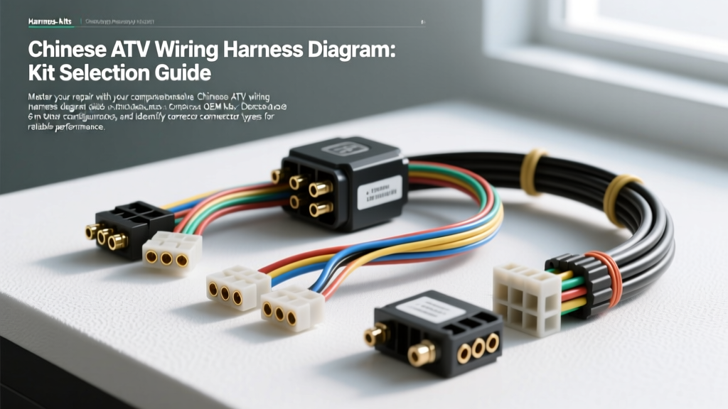
Why the Chinese ATV Wiring Harness Diagram is Your Blueprint
When restoring or repairing 110cc, 125cc, 150cc, or 200cc off-road vehicles from manufacturers like TaoTao, Kazuma, Roketa, and Sunl, the electrical system is frequently the primary point of failure. Factory harnesses are notorious for undersized wire gauges, brittle PVC insulation, and poorly crimped terminals that corrode within a single riding season. Before purchasing a replacement kit, consulting an accurate Chinese ATV wiring harness diagram is mandatory. This guide compares universal and OEM-specific harness kits, decodes standard stator pinouts, and provides actionable selection criteria to ensure your next installation doesn't result in a melted regulator plug or a dead ignition coil.
Engine Architecture: GY6 vs. CG/CB Electrical Systems
Chinese ATVs generally utilize two distinct engine families, each requiring a different harness topology. Identifying your engine type is the first step in reading your wiring diagram correctly.
- GY6 Engines (125cc-200cc): Common in buggies and some ATVs. These use a 3-phase AC stator, requiring a 3-wire (usually Yellow/Yellow/Yellow or Pink/Yellow/White) stator-to-rectifier harness. The CDI is typically DC-fired, drawing power from the battery via the ignition switch.
- CG/CB Engines (110cc-250cc): Horizontal or vertical single-cylinder engines. These predominantly use a single-phase AC stator with a dedicated lighting coil and an ignition source coil. The CDI is usually AC-fired, meaning it generates its own spark energy from the stator's Black/Red wire, independent of the battery.
If you select a harness designed for a DC-CDI system but your ATV uses an AC-CDI, the engine will not spark. Always verify your CDI type using a factory service manual or a trusted repository like Carl Salter's motorcycle and ATV manual archive before ordering.
Harness Kit Comparison: Universal vs. OEM-Specific
The aftermarket offers three primary categories of replacement harnesses. Use this comparison chart to select the right kit for your build.
| Feature | Universal 6-Pin/8-Pin Kit | OEM-Specific (e.g., TaoTao ATA150) | Heavy-Duty Stator Adapter |
|---|---|---|---|
| Best For | Custom builds, engine swaps, missing harnesses | Direct plug-and-play restoration | Fixing chronic melted stator plugs |
| Connector Types | Generic unsealed nylon (JST SM style) | OEM exact-match (Molex/KET equivalents) | Sealed automotive (Molex MX150 / Deutsch) |
| Wire Gauge (AWG) | 18-20 AWG (Often undersized) | 16-18 AWG (Factory spec) | 14-12 AWG (High current capable) |
| Installation Effort | High (Requires tracing, splicing, pin-swapping) | Low (Direct routing, labeled plugs) | Medium (Splicing at stator/rectifier only) |
| Reliability | Low to Medium | Medium | High |
Decoding the Standard 6-Pin Stator Connector
The most common failure point on a 110cc-150cc Chinese ATV is the rectangular 6-pin nylon connector linking the engine stator to the main harness. High resistance in these cheap terminals causes voltage drops, generating enough heat to melt the plastic housing. Below is the standard pinout derived from a typical CG150 Chinese ATV wiring harness diagram.
| Pin | Wire Color | Function | Min. AWG | Expected Resistance / Voltage |
|---|---|---|---|---|
| 1 | Yellow | Stator AC Output (Main Charging) | 14 AWG | 20-50V AC (at idle) |
| 2 | White | Stator AC Output (Lighting Coil) | 16 AWG | 12-30V AC (RPM dependent) |
| 3 | Blue/White | Pickup Coil Positive (+) | 18 AWG | 110 - 180 Ohms |
| 4 | Green/White | Pickup Coil Negative (-) | 18 AWG | 110 - 180 Ohms |
| 5 | Black/Red | Ignition Source Coil (AC CDI Power) | 16 AWG | 100-400V AC (Cranking) |
| 6 | Green | Stator Ground / Chassis Ground | 14 AWG | 0.0 Ohms to Block |
Expert Tip: If your harness uses 18 AWG wire for Pins 1, 2, and 5, it is fundamentally flawed. The stator outputs high amperage on the Yellow wire (often 8-12 Amps). According to SAE J1128 standards for Low Tension Primary Cable, 18 AWG wire is rated for roughly 6-8 Amps in high-temperature engine environments. Always upgrade these specific circuits to 14 AWG cross-linked polyethylene (XLPE) wire.
Wire Gauge and Connector Upgrades
When selecting a heavy-duty kit or modifying a universal harness, connector selection is just as critical as wire gauge. The factory uses open-barrel brass terminals that lack positive retention locks, leading to vibration-induced backing out and subsequent arcing.
Recommended Connector Systems
- Molex MX150 Series: Fully sealed, IP67 rated, with silicone radial shaft seals. Ideal for the stator-to-rectifier connection. Requires specific crimping tools (e.g., Molex 207900) to achieve the proper 15-20 lb crimp pull-force.
- Deutsch DT Series: Excellent for the main battery feed and starter solenoid connections. Handles up to 13 Amps per pin with rugged thermoplastic housings.
- JST SM (Upgraded): If you must use the generic white nylon connectors for the CDI or handlebar switches due to space constraints, extract the factory pins, strip the wires, and solder them directly to heavy-duty replacement pins before reinserting. Apply dielectric grease to the rubber seals to prevent moisture ingress.
Step-by-Step Selection Guide: Matching Diagram to Kit
Follow this diagnostic sequence before adding a harness kit to your cart:
- Count the Stator Wires: Open the left-side engine cover. Count the wires exiting the stator. If you see 5 wires (Yellow, White, Blue/White, Green/White, Black/Red), you have a single-phase AC system. If you see 3 Yellows and a Blue/White, you have a 3-phase system. Buy the harness that matches this exact count.
- Verify CDI Power Source: Locate the CDI box. If the main power pin on the CDI harness plug is Red (or switched 12V), you need a DC-CDI harness. If it is Black/Red, you need an AC-CDI harness. Mismatching these will result in a harness that physically plugs in but provides zero spark.
- Check the Regulator/Rectifier Plug: Chinese ATVs use either a 4-pin or 5-pin rectifier. A 4-pin uses (Yellow, Yellow, Red, Green). A 5-pin adds a White wire for the lighting coil. Ensure your selected harness has the matching rectifier pigtail.
- Inspect the Kill Switch Logic: Most Chinese ATVs use a 'ground-to-kill' logic. The Black/White wire from the handlebar switch grounds the CDI exciter coil to stop the engine. Ensure your universal harness includes this dedicated ground-kill circuit; otherwise, you will have to fabricate a custom kill loop.
Troubleshooting Mismatched or Defective Harnesses
Even with the correct Chinese ATV wiring harness diagram, installation errors occur. Use this decision tree to diagnose post-installation electrical gremlins:
- Symptom: Battery drains overnight.
- Cause: Universal harnesses often wire the Red (12V+) battery feed directly to the rectifier without a master fuse or ignition-switched relay. The rectifier's internal diodes can leak reverse current.
- Fix: Install a 15A Maxi-fuse and a 30A Bosch-style relay on the main Red wire harness feed, triggered by the ignition switch.
- Symptom: Headlights blow out at high RPM.
- Cause: The White lighting coil wire is routed directly to the headlight switch (AC lighting), bypassing the regulator. As engine RPM increases, AC voltage spikes past 40V.
- Fix: Reroute the White wire through a dedicated AC voltage regulator, or convert to a DC lighting system by feeding the headlight switch from the battery's switched 12V circuit and grounding the stator's White wire.
- Symptom: Starter solenoid clicks but won't crank.
- Cause: The main ground ring terminal (Green wire) is attached to a painted frame tab or an engine mount bolt with insufficient torque. High current draw (80-120 Amps) encounters massive resistance.
- Fix: Relocate the main harness ground to a clean, bare metal stud on the engine block. Torque the M6 ring terminal to 5-7 Nm and coat with anti-oxidant compound.
Final Thoughts on Harness Fabrication
While universal kits offer a cheap stopgap, the most reliable electrical systems on Chinese ATVs are built using OEM-style connectors paired with automotive-grade wire. By cross-referencing your specific Chinese ATV wiring harness diagram with the pinouts and AWG requirements outlined above, you can build or select a harness that outlasts the factory system by years. For detailed connector crimping techniques and terminal retention specifications, refer to the Molex MX150 application tooling guide to ensure your custom splices survive the extreme vibration of off-road riding.