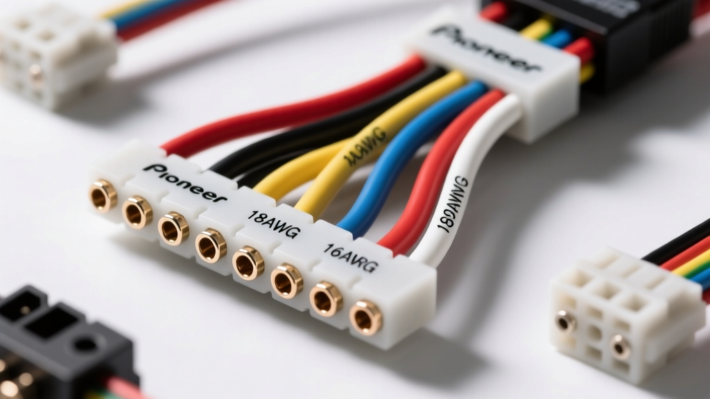
Introduction to Pioneer Harness Architecture
Integrating an aftermarket Pioneer head unit requires a precise understanding of the proprietary 16-pin power and speaker harness, alongside standard EIA (Electronic Industries Alliance) color codes. Unlike OEM factory harnesses that utilize proprietary multiplexed data buses, the standard Pioneer car audio wiring harness relies on discrete 12V power, ground, and analog speaker feeds. Misinterpreting these pinouts—particularly the constant vs. switched 12V lines—can result in catastrophic memory loss, parasitic battery drain, or blown internal audio amplifier ICs. This technical specification reference details the exact pin configurations, wire gauge (AWG) requirements, and diagnostic testing procedures for Pioneer DMH, AVH, and MVH series receivers.
Standard Pioneer 16-Pin Power and Speaker Harness
The primary interface on most modern Pioneer single-DIN and double-DIN receivers is a 16-pin block connector. This harness is typically mated to a vehicle-specific ISO adapter (such as those from Metra or Axxess) or a universal hardwire pigtail. Below is the definitive pinout reference.
| Pin | Wire Color | Function | AWG | Technical Notes |
|---|---|---|---|---|
| 1 | Yellow | +12V Constant (Battery) | 16 AWG | Supplies memory retention. Must read 12.2V-12.6V with ignition OFF. |
| 2 | Red | +12V Switched (Ignition) | 16 AWG | Triggers unit power-on. Tied to accessory relay. |
| 3 | Brown/White | Phone Mute / Nav Audio | 18 AWG | Grounding this pin mutes audio for incoming Bluetooth/Nav prompts. |
| 4 | Orange/White | Illumination / Dimmer | 18 AWG | Connects to dash lighting circuit. +12V triggers dim mode. |
| 5 | Blue/White | Amplifier Turn-On (Remote) | 18 AWG | Outputs +12V (max 300mA) when unit is powered on. |
| 6 | Blue | Power Antenna Trigger | 18 AWG | Outputs +12V only when AM/FM tuner is active. Do not use for amps. |
| 7 | Black | Chassis Ground | 16 AWG | Must terminate to bare chassis metal. Do not daisy-chain. |
| 8 | White | Front Left Speaker (+) | 18 AWG | Positive phase for FL channel. |
| 9 | White/Black | Front Left Speaker (-) | 18 AWG | Negative phase. Black tracer stripe indicates negative. |
| 10 | Gray | Front Right Speaker (+) | 18 AWG | Positive phase for FR channel. |
| 11 | Gray/Black | Front Right Speaker (-) | 18 AWG | Negative phase. |
| 12 | Green | Rear Left Speaker (+) | 18 AWG | Positive phase for RL channel. |
| 13 | Green/Black | Rear Left Speaker (-) | 18 AWG | Negative phase. |
| 14 | Purple | Rear Right Speaker (+) | 18 AWG | Positive phase for RR channel. |
| 15 | Purple/Black | Rear Right Speaker (-) | 18 AWG | Negative phase. |
| 16 | Shield/NC | Shield / Not Connected | N/A | Often left empty or used as a drain wire for RCA shielding. |
Wire Gauge (AWG) Upgrades for High-Draw Units
While the standard Pioneer harness utilizes 16 AWG wire for the primary power feeds (Pins 1, 2, and 7), this gauge is marginal for modern multimedia receivers with built-in high-current amplifiers or large illuminated screens. According to SAE International J1128 standards for low-tension primary cable, 16 AWG copper wire is rated for approximately 10-12 amps in a high-temperature engine/chassis environment.
For Pioneer AVH and DMH series units that can draw peak currents exceeding 15 amps during boot-up or heavy bass transients, voltage drop across 16 AWG wire can cause the internal protection circuit to trigger, resulting in random reboots. Expert Recommendation: Splice 12 AWG primary wire directly to the Yellow (Constant) and Black (Ground) wires within 6 inches of the harness plug. Route the 12 AWG ground wire directly to a dedicated 10mm chassis grounding bolt, torqued to 4-6 Nm, ensuring all paint and zinc coating is removed via a wire brush.
Steering Wheel Control (SWC) Resistive Ladder Wiring
Pioneer receivers interface with vehicle steering wheel controls via a 3.5mm data jack or a hardwired 3-pin SWC input. When hardwiring an adapter (such as the Axxess ASWC-1 or PAC RP5), you are dealing with a resistive ladder network.
- SWC Key 1 (Usually White/Red): Carries the primary resistor network voltage drops for Volume Up/Down and Seek.
- SWC Key 2 (Usually White/Green): Carries secondary functions (Mode, Source, Voice Command).
- SWC Ground (Usually Black): Common ground reference for the resistive ladder. Crucial: This must share a common ground plane with the radio's main black ground wire to prevent floating voltage errors that cause erratic button behavior.
When testing the OEM SWC harness before connecting the adapter, use a digital multimeter set to Ohms (Ω). Pressing a steering wheel button should yield a specific resistance drop (typically between 100Ω and 30kΩ depending on the manufacturer). If the meter reads 'OL' (Open Loop), check the clock spring rotary connector behind the steering wheel for broken flex traces.
Diagnostic Troubleshooting and Multimeter Testing
Electrical faults in aftermarket installations frequently stem from harness mismanagement. Use the following decision tree to diagnose common Pioneer harness failures:
Symptom 1: Radio Loses Presets and Clock When Ignition is Turned Off
- Cause: The Yellow (Constant 12V) and Red (Switched 12V) wires are swapped.
- Fix: Verify Pin 1 and Pin 2 at the harness block using a multimeter. With the key OFF, Pin 1 must read 12.6V. With the key ON, both Pin 1 and Pin 2 must read 12.6V. If Pin 2 reads 0V with the key OFF, the wiring is correct. Swap the connections if the logic is reversed.
Symptom 2: Alternator Whine or High-Pitched Noise in Speakers
- Cause: Ground loop induced by improper Black wire (Pin 7) termination, or RCA cables routed parallel to the power harness.
- Fix: The Pioneer harness ground must never be spliced into the cigarette lighter ground or daisy-chained to another accessory. It requires a dedicated, unpainted chassis ground. Furthermore, ensure RCA patch cables are routed down the opposite side of the vehicle's center console from the main 12V power feeds to prevent electromagnetic interference (EMI) induction.
Symptom 3: External Amplifier Fails to Turn On
- Cause: Exceeding the current limit of the Blue/White (Pin 5) remote turn-on wire.
- Fix: The internal PCB trace for Pin 5 is typically fused or limited to 300mA. If you are triggering multiple high-draw amplifiers or a DSP, the combined remote current draw will blow the internal trace. Install a standard 12V automotive 30A SPST relay. Use Pin 5 to trigger the relay coil (Terminal 86), and pull the amplifier remote turn-on from Terminal 87 (fused 12V constant).
Authoritative References and Standards
For further engineering specifications regarding automotive low-voltage wiring, terminal crimp standards, and mobile electronics integration, refer to the following resources:
- SAE International J1128: Low Tension Primary Cable - Defines the thermal and physical requirements for 16-18 AWG automotive wiring.
- Crutchfield Car Stereo Wiring Guide - Industry-standard reference for EIA aftermarket radio color codes and adapter mating procedures.
- Pioneer Official Installation Manuals - Model-specific wiring diagrams and maximum current draw specifications for AVH/DMH series receivers.