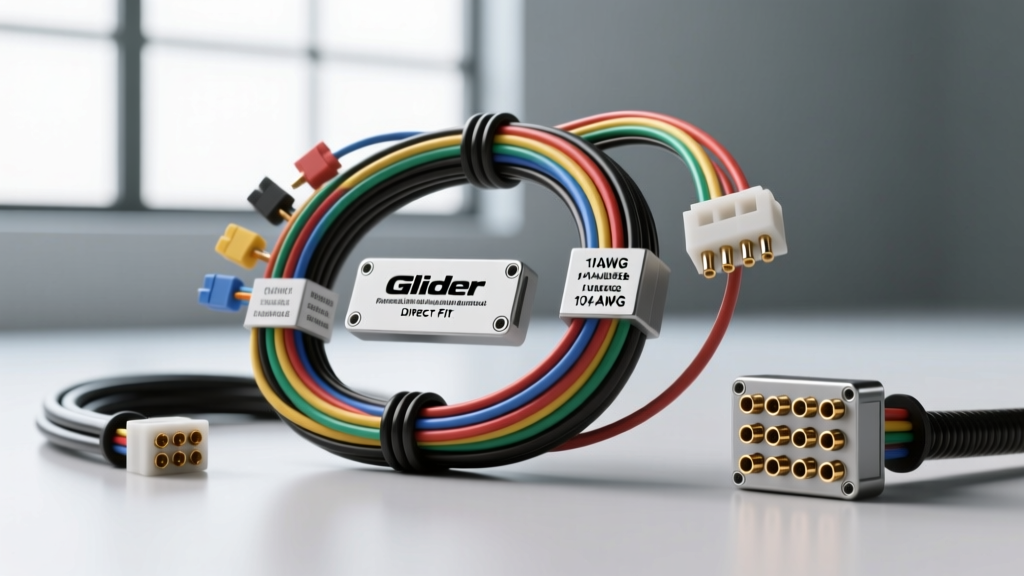
The Architecture of a Glider Kit Wiring Harness
When assembling a classic car, street rod, or custom truck from a bare chassis—commonly referred to as a glider kit—the electrical system is entirely dependent on your harness selection. A complete glider kit wiring harness is not a single monolithic component, but rather a triad of distinct circuits: the chassis harness, the engine harness, and the dash/instrument harness. Understanding how these three interact, particularly when performing a modern GM LS V8 swap into a vintage frame, is critical for long-term reliability, proper fusing, and CAN-bus integration.
Unlike OEM replacement harnesses designed for a specific factory configuration, a glider kit wiring harness must bridge the gap between vintage body accessories (headlights, wipers, HVAC) and modern powertrain control modules (PCMs). Selecting the wrong architecture will result in voltage drops, sensor interference, and catastrophic ground loop failures.
Universal vs. Direct-Fit: Which Harness Fits Your Build?
The first major decision when sourcing a glider kit wiring harness is choosing between a universal (cut-to-fit) kit and a direct-fit (vehicle-specific) kit. Universal kits, such as the Painless Performance 18-circuit or Ron Francis Bare Bones systems, provide pre-terminated fuse blocks and loose wires that you route and cut to length. Direct-fit kits, like the American Autowire Classic Update series, come with factory-style connectors pre-installed for specific vintage models (e.g., 1969 Camaro, 1957 Chevy).
| Feature | Universal Harness (e.g., Painless 10106) | Direct-Fit Harness (e.g., AAW Classic Update) |
|---|---|---|
| Installation Time | 40-60 hours (requires custom routing/crimping) | 15-25 hours (plug-and-play for OEM switches) |
| Wire Length | Extra-long; requires cutting and terminating | Pre-cut to factory chassis dimensions |
| LS Swap Integration | Highly flexible; easy to merge with standalone PCM harnesses | Requires bulkhead adapters to merge with modern engine harnesses |
| Best Application | Custom tube chassis, radical street rods, bespoke builds | OEM-restomod builds retaining factory dash and switches |
LS Swap Integration: PCM Pinouts and Power Feeds
For the majority of modern glider builds, the GM Gen III/IV LS engine is the powerplant of choice. Integrating an LS engine harness with a vintage chassis harness requires precise alignment of power, ground, and data circuits. The Powertrain Control Module (PCM) requires three primary power sources and two primary grounds to initialize and run.
Critical Gen III PCM (LS1/LS6) Pinout Requirements
- Connector C1 (Blue), Pin 19 (Pink Wire): Switched 12V Ignition. Must be sourced from a dedicated 15A ATO fuse on the chassis harness ignition bus. Do not share this circuit with high-draw accessories like electric fans.
- Connector C1 (Blue), Pin 20 (Red Wire): Constant 12V Battery. Sourced directly from the main fuse block battery feed. Essential for PCM memory retention.
- Connector C2 (Red), Pin 86 (Purple Wire): TCC Brake Switch Input. This circuit requires a 12V signal from the brake pedal switch to disengage the Torque Converter Clutch (TCC) during braking. Failure to wire this will cause the engine to stall when stopping or overheat the transmission fluid.
- Ground Pins (Black/White Wires): PCM grounds must be terminated directly to the engine block or cylinder heads using a dedicated 10 AWG ground strap, never to the chassis or body sheet metal.
For detailed routing and merging strategies, refer to the Painless Performance technical library, which provides extensive documentation on merging standalone LS harnesses with universal chassis kits.
Wire Gauge, Insulation, and SAE Standards
High-quality glider kit wiring harnesses utilize TXL (Thin-wall Cross-Linked) wire rather than standard PVC wire. TXL wire meets the SAE J1128 standard, offering a 125°C temperature rating and a significantly smaller outer diameter. This allows you to route more circuits through tight firewall grommets and vintage steering column drops without binding.
AWG Specification Chart for Custom Chassis Builds
| AWG Size | Max Ampacity (TXL) | Primary Application in Glider Builds | Fusing Requirement |
|---|---|---|---|
| 4/0 AWG | 250A+ | Battery to Starter Motor feed | 250A Mega Fuse at battery |
| 8 AWG | 60A | Main fuse block feed, Alternator output | 100A-175A Maxi / Mega Fuse |
| 10 AWG | 30A | Headlights (H4 halogen), Electric fuel pumps | 20A-30A ATO Blade Fuse |
| 12 AWG | 20A | Taillights, HVAC blower motors, Horn relay coil | 15A-20A ATO Blade Fuse |
| 14 AWG | 15A | Dash illumination, ignition switch, PCM trigger | 10A-15A ATO Blade Fuse |
Connector Selection: Weather-Pack vs. Metri-Pack
The environment under the hood of a custom build is harsh. Never use generic butt-connectors or electrical tape for engine bay connections. A premium glider kit wiring harness will utilize sealed Delphi (Aptiv) connectors.
- Weather-Pack Connectors: Ideal for high-current, low-pin-count applications such as electric cooling fans, fuel pumps, and headlight pigtails. They feature silicone rubber seals that prevent moisture ingress and handle up to 20A per cavity.
- Metri-Pack 280 Series: The standard for modern sensor connections (e.g., LS MAF sensors, O2 sensors, TPS). They offer a smaller footprint and superior vibration resistance compared to Weather-Pack connectors.
- Deutsch DT Series: Used in high-end motorsport and heavy-duty glider builds for bulkhead pass-throughs and critical ECU connections due to their positive locking mechanism and IP67 sealing.
Always use the manufacturer-specific ratcheting crimp tool (e.g., Delphi Weather-Pack crimpers) to ensure the wire barrel and insulation crimp are formed correctly. A poor crimp will increase resistance, leading to localized heat and eventual voltage drop.
Troubleshooting Common Glider Kit Harness Failures
Even with a premium harness, installation errors in custom chassis builds frequently lead to electrical gremlins. Here is a diagnostic matrix for the most common issues encountered during glider kit harness commissioning:
1. Alternator Whine in Audio Systems (Ground Loops)
Symptom: A high-pitched whine through the stereo that changes pitch with engine RPM.
Cause: The audio head unit or amplifiers are grounded to a different chassis point than the alternator or PCM, creating a ground loop where alternator AC ripple current flows through the RCA shield grounds.
Fix: Implement a star-grounding system. Run a dedicated 4 AWG ground wire from the alternator case directly to the engine block, and ensure all audio components share a single, dedicated copper ground bus tied directly to the battery negative terminal, bypassing the chassis entirely.
2. LS Engine Cranks but Will Not Inject Fuel (VATS Interference)
Symptom: Starter engages, engine turns over, but no injector pulse is detected.
Cause: The Vehicle Anti-Theft System (VATS) or Passlock II security module is active in the donor PCM and is not receiving the correct resistance signal or serial data from the original ignition cylinder.
Fix: Have the PCM flashed with a 'VATS Delete' tune to disable the security protocol entirely, which is the standard practice for glider kit LS swaps. Alternatively, wire a VATS bypass module that mimics the resistance pellet of the original key.
3. Dimming Headlights at Idle
Symptom: Headlights dim significantly when the engine is idling or when the electric cooling fans engage.
Cause: Undersized main power feeds or poor battery-to-chassis grounding. If the main 8 AWG feed from the alternator to the fuse block is too long or damaged, voltage drop will exceed 0.5V under load.
Fix: Upgrade the alternator-to-fuse-block feed to 6 AWG or 4 AWG wire. Ensure the headlight relays are triggered directly from the fuse block, and the high-current headlight loads are fed by a dedicated relay harness connected directly to the battery via a 30A Maxi fuse.
For more comprehensive routing and fusing strategies, consult the American Autowire routing and best practices guide. Proper planning of your glider kit wiring harness layout before cutting a single wire will save dozens of hours of diagnostic troubleshooting on the dyno and the street.