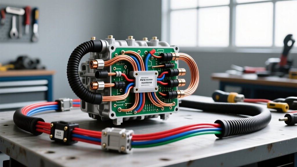
The Architecture of the 6.0L Powerstroke Electrical System
The 6.0L Powerstroke (Navistar VT365) utilizes a highly complex, split-voltage electrical architecture. Unlike traditional 12V diesel systems, the 6.0L relies on a Fuel Injection Control Module (FICM) to step up chassis voltage to 48V for actuating the hydraulic spool valves in the fuel injectors. When performing a 6.0 Powerstroke engine wiring harness replacement, technicians must navigate both the standard 12V logic circuits and the high-current 48V injection circuits. The main engine harness (MEH) routes from the 104-pin Powertrain Control Module (PCM) through the firewall, branching out to the FICM, alternator, glow plug control module (GPCM), and various engine sensors. Due to extreme under-hood temperatures and high-frequency vibration, the OEM harness is prone to specific failure modes that require precise diagnostic validation before full replacement.
Primary Failure Vectors in the 6.0L Main Harness
FICM Power and Logic Circuit Chafing
The most catastrophic failure point in the 6.0L wiring ecosystem is the FICM harness routing. The OEM harness secures to the FICM bracket and the left-hand valve cover. Over time, the corrugated loom degrades from radiant heat (often exceeding 220 degrees Fahrenheit near the turbocharger up-pipes). Once the loom splits, the 12V logic wires and 48V injector return wires chafe against the sharp aluminum edges of the FICM bracket. This causes a dead short to ground, instantly destroying the FICM logic board and throwing P0611 or P0201-P0208 injector circuit codes. A proper replacement requires upgrading the harness routing and applying high-temp fiberglass sleeving.
Under-Valve-Cover Injector Harness Degradation
While technically a separate sub-harness, the under-valve-cover harness (UVCH) mates directly to the main engine harness via the valve cover grommets. The UVCH is submerged in engine oil, which routinely reaches 230 degrees Fahrenheit under heavy load. The OEM Teflon-insulated wires become brittle, and the injector spool valve pins corrode. When replacing the main engine harness, it is mandatory to inspect the UVCH pigtails. If the 18 AWG injector wires show micro-fractures at the crimp barrel, the entire UVCH must be replaced concurrently to prevent misfire codes post-repair.
FICM and Injector Circuit Pinout Specifications
Understanding the pinout is critical when depinning connectors for custom routing or verifying continuity during a 6.0 Powerstroke engine wiring harness replacement. The FICM utilizes four primary connectors: X1 and X2 (16-pin injector circuits) and X3 and X4 (4-pin power and logic). Below is a reference chart for the critical FICM X3 power connector and the Injector 1 circuit.
| Connector / Pin | Wire Color | AWG | Circuit Function | Voltage Spec |
|---|---|---|---|---|
| X3 Pin 1 | Yellow/White | 16 AWG | IGN Power (Run/Start) | 12.0V - 14.5V |
| X3 Pin 2 | Red/Light Green | 12 AWG | Battery Power (B+ Main) | 12.0V - 14.5V |
| X3 Pin 3 | Black/White | 12 AWG | Power Ground | < 0.1V Drop |
| X1 Pin 1 | Dark Green/Orange | 18 AWG | Injector 1 Return | 48V Pulse |
| X1 Pin 2 | White/Red | 18 AWG | Injector 1 Supply | 48V Pulse |
Technical Note: The OEM B+ feed to the FICM (Red/Light Green) is 12 AWG. Many advanced electrical technicians upgrade this specific circuit to 8 AWG during a harness replacement to mitigate voltage drop, ensuring the FICM internal capacitors receive maximum amperage during extended cranking events.
Comprehensive Harness Replacement Protocol
Phase 1: Teardown and Connector Extraction
Begin by disconnecting both negative battery cables. The 6.0L utilizes dual alternators and high-capacity FICM capacitors; failing to isolate the chassis can result in severe arcing at the PCM connectors. Remove the cowl panel, degas bottle, and the turbocharger assembly to access the rear harness pass-through near the EGR cooler. When disconnecting the 104-pin PCM connector, use a specialized terminal release tool to depress the secondary locking tab. Never pull by the wire pigtails. For the FICM connectors, slide the red locking wedge outward before depressing the primary tab. Inspect the male pins on the FICM and PCM for fretting corrosion, which appears as a dark, powdery residue. Clean with electrical contact cleaner and apply a pea-sized amount of Motorcraft XC-99 dielectric grease to the connector seals.
Phase 2: Routing and Heat Shielding
Route the new main engine harness along the factory chassis clips, ensuring a minimum 2-inch clearance from the exhaust manifolds and turbocharger. The 6.0L engine harness features hard plastic loom retainers that snap into the cylinder head. If these retainers are brittle, replace them with updated stainless steel P-clips to prevent future chafing. At the firewall bulkhead connector, verify that the silicone weather seal is fully seated. A compromised bulkhead seal allows water intrusion into the cabin-side PCM harness, leading to CAN-bus communication faults (U0100 codes). Secure all 18 AWG injector branches with high-temperature Tesa tape rather than standard PVC electrical tape, which will melt and leave a corrosive adhesive residue on the valve covers.
Post-Installation Validation and Voltage Drop Testing
Do not immediately start the engine after completing the 6.0 Powerstroke engine wiring harness replacement. Reconnect the batteries and perform a static voltage drop test across the FICM power and ground circuits. Set your digital multimeter to DC millivolts. Place the positive probe on the battery positive post and the negative probe on the FICM X3 Pin 2 cavity (back-probing the connector). Crank the engine. The voltage drop must not exceed 0.1V (100mV). A reading higher than 0.2V indicates excessive resistance in the new harness or a poor chassis ground, which will starve the FICM and cause injector stiction. Next, monitor the ICP (Injection Control Pressure) sensor signal. The ICP is a 3-wire sensor (5V reference, signal return, and ground). With Key-On-Engine-Off (KOEO), the ICP signal wire (Light Blue/White) should read exactly 0.25V to 0.30V. If the new harness has a pinched 5V reference line, this voltage will skew, causing a no-start condition.
Authoritative References
- Ford Motorcraft Service Portal - PC/ED Wiring Diagrams and Pinpoint Tests for 6.0L Powerstroke.
- SAE J1113 Electromagnetic Compatibility Standards - Guidelines for high-frequency wiring routing and shielding in diesel applications.
- Navistar VT365 Technical Service Bulletins - OEM engineering specifications for FICM voltage thresholds and injector solenoid resistance.