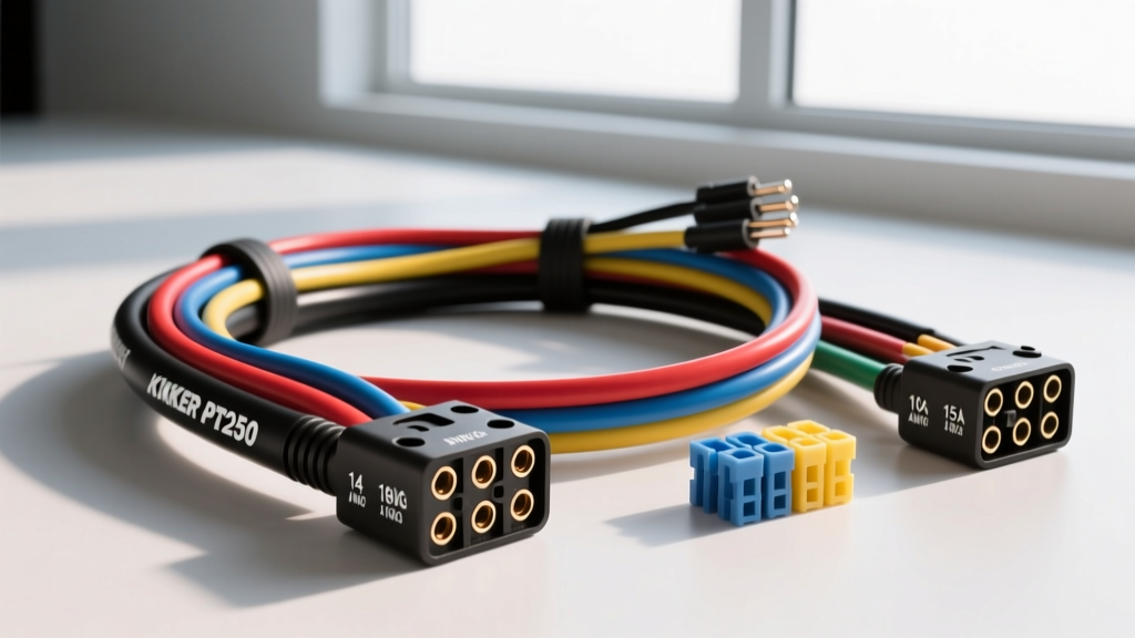
Introduction to the Kicker PT250 Wiring Harness System
The Kicker PT250 powered subwoofer system requires a precise, low-resistance electrical pathway to deliver its rated 250 watts of RMS output without inducing thermal throttling or voltage sag. Unlike passive subwoofer enclosures that rely on an external amplifier's harness, the PT250 utilizes an integrated amplifier plate with a specific wiring harness topology. Understanding the exact specifications of the Kicker PT250 wiring harness is critical for mobile electronics installers and DIY enthusiasts aiming to achieve optimal acoustic output and long-term component reliability. This technical reference outlines the mandatory wire gauges, pinout configurations, signal integration protocols, and termination standards required for a factory-grade installation.
Power and Ground Wire Specifications (CTA-2015 Compliance)
The internal amplifier of the PT250 can draw upwards of 22 amps at peak transient bursts. To prevent voltage drop below the amplifier's undervoltage protection threshold (typically 10.5V DC), the power and ground harness segments must adhere strictly to the Consumer Technology Association's CTA-2015 Mobile Electronics Cabling Standard. Using undersized wire or Copper Clad Aluminum (CCA) will result in excessive resistance, causing the PT250 to enter protection mode during heavy bass transients.
For the main power harness run from the vehicle's battery to the PT250 enclosure, 8 AWG Oxygen-Free Copper (OFC) wire is mandatory for runs exceeding 10 feet. For runs under 10 feet, 10 AWG OFC is the absolute minimum, though 8 AWG remains the industry best practice to accommodate future system upgrades and minimize resistive heating. The ground harness segment must be identical in gauge to the power wire and should never exceed 36 inches in length to maintain a low-impedance path to the vehicle's chassis.
| Parameter | Specification | Technical Notes |
|---|---|---|
| Power Wire Gauge | 8 AWG OFC (Minimum) | Stranding: ~735 strands of 30 AWG. Avoid CCA wire entirely. |
| Inline Fuse Rating | 25A ATC/ATO Blade | Must be installed within 18 inches of the battery positive terminal. |
| Ground Wire Gauge | 8 AWG OFC | Max length 36 inches. Must terminate to bare, unpainted chassis metal. |
| Insulation Material | PVC or XLPE | Must meet SAE J1128 low-tension primary cable temperature ratings. |
| Voltage Drop Tolerance | < 0.25V DC | Measured at the amp terminal block under maximum RMS load. |
Kicker PT250 Wiring Harness Pinout & Color Code Reference
The Kicker PT250 utilizes a multi-conductor harness for signal, remote turn-on, and auxiliary power distribution. When interfacing with the amplifier's terminal block or utilizing the proprietary Molex-style connector found on certain Kicker harness adapters, adhering to the standard mobile electronics color code is essential for diagnostic troubleshooting and preventing catastrophic short circuits.
| Wire Color | Function | Gauge | Destination / Source |
|---|---|---|---|
| Red | Constant 12V+ Power | 8 AWG | Vehicle Battery (via 25A inline fuse) |
| Black | Chassis Ground | 8 AWG | Vehicle Chassis (bare metal, star washer) |
| Blue w/ White Stripe | Remote Turn-On | 18 AWG | OEM Radio Amp Turn-On or Fuse Box Add-A-Circuit |
| Gray | Front Left Speaker (+) | 16 AWG | OEM Head Unit or Factory Amplifier Output |
| Gray w/ Black Stripe | Front Left Speaker (-) | 16 AWG | OEM Head Unit or Factory Amplifier Output |
| White | Front Right Speaker (+) | 16 AWG | OEM Head Unit or Factory Amplifier Output |
| White w/ Black Stripe | Front Right Speaker (-) | 16 AWG | OEM Head Unit or Factory Amplifier Output |
Signal Input Harness: RCA vs. Speaker-Level Integration
The Kicker PT250 wiring harness must be configured to accept either low-level (RCA) or high-level (speaker wire) signals, depending on the vehicle's existing audio topology. When integrating with an aftermarket head unit, standard dual-channel RCA cables should be routed through the vehicle's opposite-side chassis rail to prevent electromagnetic interference (EMI) from the 8 AWG power harness.
For OEM radio integration, where low-level preouts are unavailable, the harness requires a speaker-level to line-level converter. Kicker's proprietary KISL (Kicker Interconnect Speaker Level) adapter is highly recommended for this application. The KISL harness splices directly into the 16 AWG speaker output wires listed in the pinout table above and converts the high-voltage speaker signal into a clean, low-impedance RCA output. Crucially, the KISL adapter also features a signal-sense circuit that generates a 12V remote turn-on signal when audio is detected, eliminating the need to tap into a dedicated remote wire in modern CAN-bus vehicles.
Remote Turn-On Circuit and Signal Sense Technology
The 18 AWG Blue/White remote turn-on wire in the Kicker PT250 wiring harness requires a +12V DC signal to disengage the amplifier's standby mode and activate the switching power supply. In traditional installations, this is sourced from the head unit's antenna trigger or amplifier turn-on lead. However, in late-model vehicles equipped with Class D factory amplifiers and digital signal processing (DSP), the factory remote turn-on wire may pulse or drop voltage after the initial boot sequence.
If the PT250 shuts off intermittently during playback in a late-model vehicle, the harness must be reconfigured to use a DC Offset Signal Sense circuit. The PT250's internal circuitry monitors the high-level speaker inputs for a DC offset voltage (typically between 1.5V and 3.0V) generated by OEM Class D amplifiers. By setting the internal input switch to 'High Level' and utilizing the speaker-level harness pins, the PT250 will automatically detect the audio signal or DC offset and power on, rendering the 18 AWG Blue/White remote wire completely unnecessary. If the remote wire must be used, verify the source wire maintains a steady 11.5V to 14.4V under load using a digital multimeter.
Terminal Termination, Crimping, and Torque Specifications
A frequent failure point in the Kicker PT250 wiring harness is improper termination at the amplifier's terminal block. The 8 AWG power and ground wires must be terminated using closed-barrel, nylon-insulated ring terminals. Open-barrel or indent crimps are unacceptable for high-current mobile audio applications as they allow moisture ingress and suffer from high contact resistance.
Installers must use a dedicated hexagonal crimping die sized specifically for 8 AWG terminals. The crimp should deform the terminal barrel evenly around the copper strands without cutting or severing the outer strands. Once crimped, the ring terminal should be secured to the PT250's terminal block. The brass set screws on the Kicker amplifier terminal block are relatively soft and prone to stripping. The recommended torque specification for these terminal block screws is 1.5 Nm to 2.0 Nm (approximately 13 to 18 inch-pounds). Over-torquing will strip the brass threads, rendering the amplifier plate defective and voiding the warranty.
Diagnostic Troubleshooting for PT250 Harness Faults
When diagnosing a Kicker PT250 that fails to power on or produces excessive alternator whine, the wiring harness is the primary suspect. Follow this structured diagnostic sequence:
- Alternator Whine (Ground Loop): If a high-pitched whine increases with engine RPM, the 8 AWG ground harness is likely terminating to a painted surface or a shared ground point with a noisy ECU module. Relocate the ground to a dedicated, bare-metal chassis point and apply dielectric grease to prevent oxidation.
- Thermal Protection Mode: If the PT250 red LED indicator flashes during heavy bass hits, perform a voltage drop test across the 8 AWG power harness. Place the multimeter's red probe on the battery positive terminal and the black probe on the amplifier's positive terminal block. If the voltage drop exceeds 0.25V while the system is playing at 75% volume, the power wire is either undersized, made of CCA, or the inline fuse holder has corroded contacts.
- No Power / Standby Mode: Verify the 25A ATC inline fuse near the battery. If the fuse is intact, check the 18 AWG Blue/White remote wire for a minimum of 10.5V DC when the ignition is in the 'ON' position. If voltage is absent, tap into an ignition-switched fuse in the cabin fuse box using a high-quality Add-A-Circuit harness adapter.
Authoritative References
For further reading on mobile electronics cabling standards and automotive wire specifications, consult the following authoritative resources:
- Consumer Technology Association (CTA) - CTA-2015 Mobile Electronics Cabling Standard guidelines for OFC wire and current capacity.
- SAE International - SAE J1128 Low Tension Primary Cable standards for automotive wire insulation and temperature ratings.
- Kicker Mobile Audio - Official PT250 powered enclosure owner's manual and technical support bulletins for terminal torque specs.