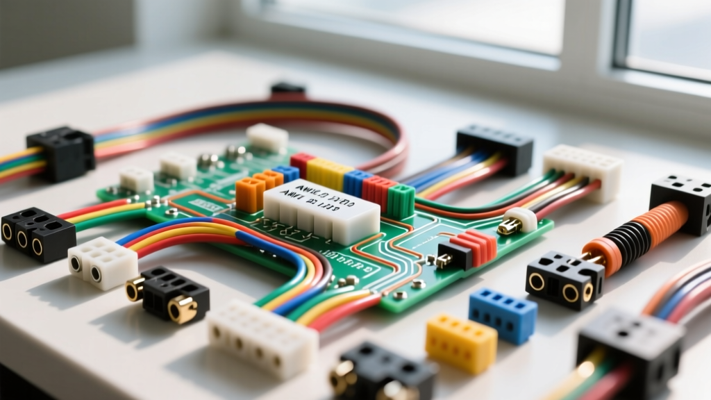
Decoding the EZ Wiring Harness Diagram: A Professional Walkthrough
Installing a universal 21-circuit harness in a classic muscle car or custom hot rod requires more than just connecting matching wire colors. A comprehensive EZ Wiring harness diagram serves as the blueprint for your vehicle's entire electrical nervous system. Unlike OEM harnesses that rely on complex, multi-layered bulkhead connectors and proprietary computer modules, the EZ Wiring system utilizes a centralized, fused power distribution block with color-coded, labeled circuits. This guide provides an expert-level walkthrough of the core circuits, AWG specifications, and critical junction pinouts required to execute a flawless, fire-safe installation.
Central Fuse Block: Circuit Allocation and AWG Specifications
The heart of the EZ Wiring system is the 21-circuit fuse panel. Understanding the load requirements of each circuit dictates the wire gauge used from the factory. According to SAE Standard J1128 for low-tension primary cable, wire gauge must be selected based on the maximum continuous current draw and the physical length of the run to prevent excessive voltage drop. Below is the standard allocation for the primary EZ Wiring fuse block.
| Circuit | Function | Wire Color | AWG | Fuse Rating |
|---|---|---|---|---|
| 1 | Headlights (High/Low) | Yellow / Blue / Green | 10 AWG | 20A |
| 2 | Tail, Marker, & Dash Lights | Brown | 12 AWG | 15A |
| 3 | Wipers & Washer Motor | Dark Green | 12 AWG | 15A |
| 4 | Radio / Accessory Feed | Purple | 14 AWG | 10A |
| 5 | Cigarette Lighter / Aux 12V | Orange | 12 AWG | 20A |
| 6 | Heater / A/C Blower Motor | Light Blue | 10 AWG | 25A |
| 7 | Turn Signals & Hazard Flashers | Light Green / Dark Blue | 14 AWG | 15A |
| 8 | Brake Light Switch Feed | White | 14 AWG | 15A |
| 9 | Horn & Dome Light | Red (Constant) / White | 12 AWG | 15A |
| 10 | Ignition Switch Feed (BAT) | Red | 10 AWG | 30A |
| 11 | Electric Cooling Fan Relay | Pink (Switched) | 12 AWG | 15A |
| 12 | Fuel Pump (EFI/Carb) | Pink | 12 AWG | 15A |
| 13 | Engine Instruments (Gauges) | Pink | 14 AWG | 10A |
| 14 | Transmission / Overdrive | Pink | 14 AWG | 10A |
| 15 | Backup Lights | Light Green | 14 AWG | 10A |
| 16 | Power Windows / Seats | Red (Constant) | 10 AWG | 30A |
Note: Always use a high-quality thermal circuit breaker for high-amperage constant feeds (like power seats or winches) rather than standard glass fuses, which are prone to fatigue failure under sustained heavy loads.
Headlight, Dimmer, and Turn Signal Switch Routing
Headlight Circuit and Dimmer Integration
The EZ Wiring harness diagram routes the primary headlight feed via a 10 AWG Yellow wire to the headlight switch. From the switch, the high-beam and low-beam feeds exit to the floor-mounted or column-mounted dimmer switch. The standard 3-pin dimmer connector utilizes:
- Pin 1 (Feed): Yellow (10 AWG) from the headlight switch.
- Pin 2 (Low Beam): Green (12 AWG) routing to the headlight buckets.
- Pin 3 (High Beam): Blue (12 AWG) routing to the headlight buckets and the high-beam indicator light on the dash.
When upgrading to modern H4 halogen or LED sealed beams, the current draw on the Green and Blue wires may exceed the capacity of the factory headlight switch contacts. It is highly recommended to install a dual-headlight relay kit, using the EZ Wiring Green and Blue wires merely as trigger signals (drawing less than 0.5A) for the relay coils, while pulling the heavy 10 AWG load directly from the battery via a dedicated fused feed.
GM-Style Column Turn Signal Switch Pinout
Integrating a GM-style steering column requires mating the EZ Wiring harness to the column's 9-pin or 7-pin connector. The most common failure mode in custom builds is crossed turn signal and brake light circuits. Refer to this standard GM column mapping when splicing:
- Purple: Turn signal flasher feed.
- Light Blue: Right front turn signal.
- Dark Blue: Right rear turn signal & brake light.
- Yellow: Left front turn signal.
- Dark Green: Left rear turn signal & brake light.
- White: Brake light switch feed (enters the column, gets interrupted by the turn signal switch during cornering).
- Brown: Hazard flasher feed.
Ignition Switch and Neutral Safety Switch Logic
The ignition circuit is where most novice installers cause severe electrical damage. The EZ Wiring harness provides a heavy 10 AWG Red wire for the main Battery (BAT) feed to the ignition switch. The switch then distributes power to three distinct outputs:
- IGN (Pink Wire): Energizes the coil, ECU, fuel pump relay, and gauge cluster in the 'Run' and 'Start' positions.
- ACC (Brown Wire): Powers the radio and wipers in the 'Accessory' and 'Run' positions, but drops out during 'Start' to preserve cranking voltage.
- ST (Yellow/Purple Wire): The starter solenoid trigger wire. This wire must be routed through a Neutral Safety Switch (NSS) on automatic transmissions or a clutch interlock switch on manuals.
According to Bosch Automotive Electrics guidelines, the starter solenoid draw can spike to 30-40 amps momentarily. Ensure the ST wire uses a minimum of 12 AWG and that the NSS contacts are rated for at least 50A continuous to prevent the switch from welding shut, which would result in the starter engaging while the engine is already running. Additionally, route the Pink IGN wire away from exhaust headers, as prolonged heat exposure increases copper resistance and causes voltage drop at the ECU.
Alternator Integration: 1-Wire vs. 3-Wire GM Setups
The EZ Wiring harness diagram includes provisions for both 1-wire and 3-wire alternators. If you are using a GM 12SI or CS130 3-wire alternator, the harness provides a Red (BAT), Pink (Ignition/Excite), and White (Sense) wire. The CS130 requires a specific 2-pin Metri-Pack 150 series connector.
- BAT (Red, 10 AWG): Connects directly to the alternator output stud and the battery positive.
- Excite (Pink, 14 AWG): Connects to Pin 1 on the alternator. This wire must be switched (key-on) to provide the initial electromagnetic field to begin charging.
- Sense (White, 14 AWG): Connects to Pin 2. This wire should be routed directly to the battery positive or the main fuse block positive bus, not simply jumped to the alternator BAT post. Jumping it locally causes the internal regulator to read alternator output voltage rather than actual battery state-of-charge, leading to undercharging at idle.
Troubleshooting Common Harness Diagram Misinterpretations
Symptom: Dash Lights Flicker with Turn Signals
Cause: Inadequate grounding at the instrument cluster or tail light housings. When the tail light ground fails, the turn signal current backfeeds through the dash illumination circuit (Brown wire) seeking a path to ground.
Fix: Run dedicated 12 AWG Black ground wires from the instrument cluster housing and both tail light buckets directly to the chassis. Never rely on rusty sheet metal screws for ground paths. Use star washers to bite through paint and apply dielectric grease to prevent galvanic corrosion.
Symptom: Starter Solenoid Stays Engaged After Engine Starts
Cause: The ST (Purple/Yellow) wire is shorted to the IGN (Pink) circuit, or the Neutral Safety Switch contacts have welded together due to arcing.
Fix: Test for continuity between the ST wire and ground with the key in the 'Run' position. If continuity exists, trace the short. To protect the NSS and ignition switch from high inductive spikes, install a standard 12V automotive relay (Bosch-style 5-pin) where the ignition switch triggers the relay coil, and the relay contacts handle the 40A starter solenoid load.
Symptom: Voltage Drop at the Headlights
Cause: Using the factory headlight switch to carry 20+ amps of continuous load over 15 feet of wire results in significant voltage drop, dimming the lights.
Fix: Install a heavy-duty headlight relay harness. Use the EZ Wiring diagram's headlight feeds solely as low-amperage triggers for the relays, and pull the main headlight power from a dedicated 40A circuit breaker mounted within 18 inches of the battery positive terminal.
Authoritative References
- SAE International. (2021). J1128: Low Tension Primary Cable. Society of Automotive Engineers.
- Halderman, J. D. (2019). Automotive Electricity and Electronics (6th ed.). Pearson. (Reference for voltage drop calculations and GM column pinouts).
- National Fire Protection Association. (2020). NFPA 70: National Electrical Code (Adapted principles for mobile DC power distribution and overcurrent protection).