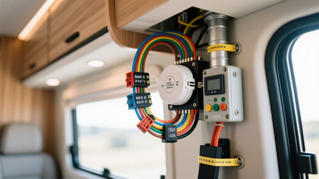
Introduction to 12V RV Smoke Detection Systems
While standard residential smoke detectors rely on 9V batteries or 120V AC mains, Class A, B, and C motorhomes require specialized 12V DC hardwired life-safety systems. According to the NFPA 1192 Standard on Recreational Vehicles, hardwired smoke detectors must be connected to the vehicle's house battery system with a dedicated power feed and an interconnect loop. This ensures that if a fire starts in the rear bedroom, the alarm in the front cockpit will simultaneously trigger, waking the occupants regardless of where they are sleeping.
Installing a dedicated smoke detector wiring harness kit is not as simple as splicing into a nearby 12V ceiling light. Improper harness routing, inadequate wire gauges, and poor grounding can lead to voltage drops, false alarms, or catastrophic failure during an emergency. This practical how-to guide will walk you through the proper installation, termination, and integration of a 12V hardwired smoke detector harness in a motorhome environment.
Anatomy of a 12V Smoke Detector Wiring Harness
A premium RV smoke detector harness kit typically features a 4-pin Molex Micro-Fit 3.0 or JST SM series connector. This allows for easy detector replacement without having to cut and re-crimp wires in the ceiling cavity. Below is the standard pinout and wire specification chart for a 4-wire RV smoke alarm harness.
| Pin | Wire Color | AWG Size | Function | Termination Point |
|---|---|---|---|---|
| 1 | Red | 16 AWG | 12V+ Constant Power | House DC Fuse Panel (2A/3A Mini-ATM) |
| 2 | Black | 16 AWG | Chassis/House Ground | Star Ground Bus Bar or Chassis Stud |
| 3 | Yellow | 18 AWG | Interconnect Signal (Daisy-Chain) | Pin 3 of Secondary Detectors |
| 4 | White | 18 AWG | Alarm Trigger / Relay Output | RV-C Multiplexer or BMS Alert Input |
Note: Wire insulation should meet SAE J1128 standards (GXL or TXL type) to withstand the high-temperature environments found near RV roof vents and HVAC ducting.
Pre-Installation Preparation and Safety Protocols
Before pulling any wire through your motorhome's ceiling joists or sidewalls, strict safety and preparation protocols must be followed to prevent short circuits and ensure long-term reliability.
- Disconnect Power: Turn off the main house battery disconnect switch and remove the negative terminal from the house battery bank to eliminate the risk of dead shorts.
- Map the Route: Plan your harness routing to avoid high-current DC lines (such as inverter cables or solar charge controller feeds). Running low-voltage signal wires parallel to high-amperage cables can induce Electromagnetic Interference (EMI), causing the smoke detector's photoelectric sensor to trigger false alarms.
- Calculate Voltage Drop: A typical hardwired RV smoke detector draws 40mA in standby and up to 150mA during an alarm event. If you are daisy-chaining four detectors across a 40-foot Class A motorhome, the cumulative resistance of 18 AWG wire can cause a voltage drop at the final unit. For main feeds exceeding 20 feet, always step up to 16 AWG or 14 AWG for the Red (12V+) and Black (Ground) wires to ensure the last detector receives no less than 11.5V.
Step-by-Step Harness Routing and Connection
Step 1: Main Power Feed Integration
Route the Red 16 AWG wire from your house DC distribution panel to the location of the primary smoke detector. Install a dedicated 2A or 3A Mini-ATM fuse in the panel. Do not share this circuit with LED lighting or water pumps, as voltage spikes from inductive loads (like pump motors) can damage the detector's internal logic board. Use an adhesive-lined polyolefin heat shrink ring terminal (3M MDT series) for the panel connection to prevent moisture ingress and vibration-induced strand breakage.
Step 2: Routing the Interconnect Loop
The Yellow 18 AWG interconnect wire is the backbone of your life-safety system. Run this wire from the primary detector to all secondary detectors (bedroom, bunkhouse, kitchen). When passing through metal chassis bulkheads or aluminum framing, always use rubber grommets to prevent the wire insulation from chafing against sharp edges, which is a leading cause of ground faults in RV harnesses.
Step 3: Grounding Best Practices
Never ground a smoke detector harness to a random sheet metal screw in the ceiling. The RV roof and upper sidewalls are often poorly bonded to the main chassis ground, leading to 'ground loops' and erratic detector behavior. Route the Black ground wire down the sidewall (inside the wire mold or behind cabinetry) and terminate it at a dedicated, cleaned, and dielectric-greased chassis ground stud or a centralized house ground bus bar.
Step 4: Connector Termination
When terminating the harness to the Molex or JST connector block, use a precision ratcheting crimp tool (such as the IWISS IWS-16 or equivalent). A proper crimp should pass a pull-test of at least 15 lbs. After crimping the pins, slide the connector housing together until you hear a definitive click, ensuring the secondary locking tang is engaged.
Advanced Integration: BMS and RV-C Multiplexer Tie-Ins
Modern motorhomes utilize LIN-based RV-C networks or centralized Battery Management Systems (BMS) to monitor vehicle status. The White wire on your smoke detector harness provides a 12V+ output only when the alarm is actively sounding. By splicing this wire into a digital input on an RV-C multiplexer (like a Spyder or Magnum ME-ARC node), you can program the system to execute emergency macros. For example, an alarm trigger can automatically unlock all power door locks, illuminate interior egress lighting, and send a push notification to the owner's smartphone via the RV's telematics router. This level of integration transforms a simple wiring harness into a comprehensive fleet safety network.
Troubleshooting Common Harness and Detector Faults
Even with meticulous installation, RV electrical systems are prone to unique environmental stressors. Use this diagnostic tree to troubleshoot harness-related issues.
- Symptom: Intermittent 'Low Battery' chirp despite being hardwired.
Cause: Voltage drop at the detector terminals due to undersized wire, poor ground, or a corroded inline fuse holder.
Fix: Measure voltage directly at the harness connector pins while the detector is under load. If it reads below 11.8V, upgrade the harness to 14 AWG and clean the ground bus bar. - Symptom: False alarms occurring only during the day.
Cause: EMI from the solar charge controller's PWM/MPPT switching frequency interfering with the detector's ionization or photoelectric chamber.
Fix: Re-route the harness away from solar DC feeds. If re-routing is impossible, wrap the detector harness in a copper-braided EMI shielding sleeve and ground the shield at one end only. - Symptom: Primary detector sounds, but secondary detectors remain silent.
Cause: Broken Yellow interconnect wire or a backed-out pin in the Molex connector.
Fix: Use a multimeter to test continuity on the Yellow wire between units. Inspect the connector housing for pins that were not fully seated during the crimping process.
Expert Tips for Long-Term Harness Reliability
The RV Industry Association (RVIA) emphasizes that vibration and thermal cycling are the primary enemies of automotive wiring harnesses. To ensure your smoke detector harness lasts the lifetime of the motorhome, avoid soldering wire splices in the ceiling cavity. Solder creates a rigid joint that can fatigue and crack under the constant micro-vibrations of highway travel. Instead, rely exclusively on high-quality, ratcheting crimps sealed with dual-wall adhesive heat shrink. Finally, secure the harness to the ceiling joists every 12 inches using UV-resistant nylon cable ties or P-clips, preventing the wire from sagging and resting against hot HVAC ductwork or recessed lighting fixtures.