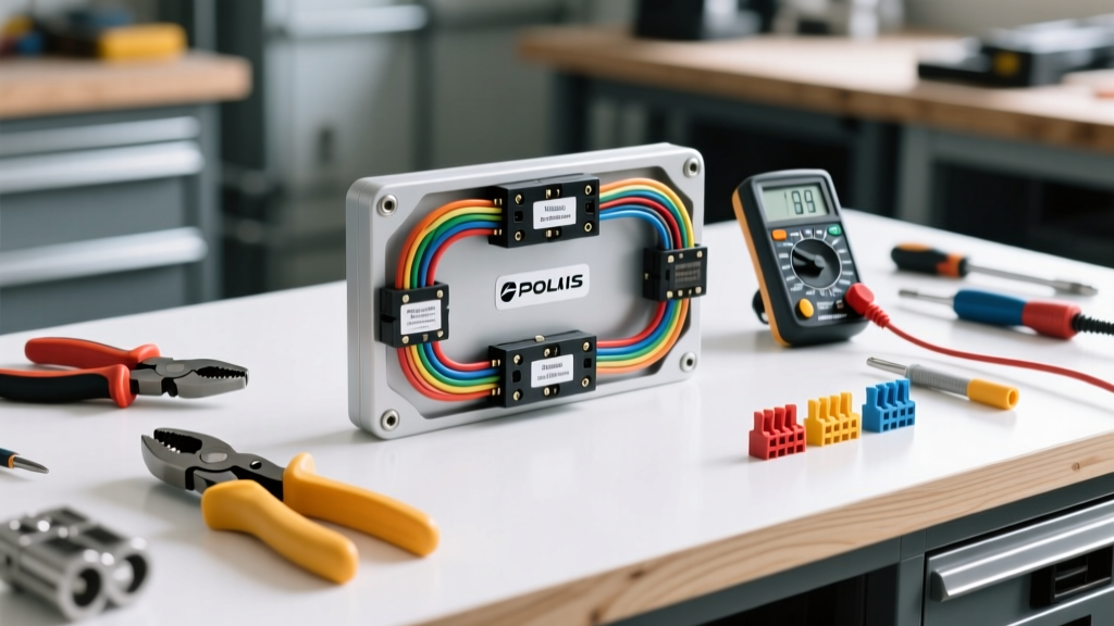
Introduction to the Polaris Pulse Bar Electrical Ecosystem
Equipping a Polaris RZR, General, or Ranger with a pulse bar—commonly utilized for LED chase lights, strobe modules, and roof-mounted accessory racks—requires a robust electrical foundation. The off-road environment subjects wiring to extreme high-frequency vibration, water ingress, and abrasive debris. A substandard Polaris pulse bar wiring harness will inevitably lead to voltage drops, flickering LEDs, or catastrophic short circuits. This comprehensive analysis breaks down the financial investment and precise tooling required to install, repair, or fabricate a harness capable of surviving the rigorous demands of UTV operation.
Financial Breakdown: OEM vs. Aftermarket vs. Custom Fabrication
When budgeting for a pulse bar lighting setup, the wiring harness is often an overlooked line item. The cost varies drastically depending on whether you opt for factory-engineered solutions, plug-and-play aftermarket kits, or a ground-up custom fabrication. Below is a comparative analysis of the three primary routes.
| Harness Type | Estimated Cost | Pros | Cons & Limitations |
|---|---|---|---|
| OEM Polaris Accessory Harness | $110 - $160 | Direct plug-and-play into factory busbars; maintains factory warranty; pre-loomed with exact OEM routing clips. | Highest upfront cost; limited to specific Polaris accessory part numbers; often lacks integrated inline fusing for high-draw pulse strobes. |
| Aftermarket Plug-and-Play | $45 - $85 | Cost-effective; usually includes a 30A relay, inline ATC fuse, and pre-crimped Weather-Pack or Deutsch connectors. | Wire routing may require zip-ties instead of factory clips; wire gauges are sometimes undersized (16 AWG instead of 14 AWG). |
| Custom DIY Fabrication | $25 - $45 | Complete control over wire gauge (TXL/GXL); exact length customization; highest reliability if crimped correctly. | Requires specialized crimping tools and technical knowledge; time-consuming; no plug-and-play convenience. |
Essential Tooling for Harness Installation and Repair
If you choose the custom fabrication route or need to repair a damaged OEM Polaris pulse bar wiring harness, standard household tools will not suffice. The UTV environment requires connections that meet SAE J1128 and USCAR-2 standards for vibration and moisture resistance. Using improper tools leads to cold crimps, which increase electrical resistance and generate heat.
1. Precision Wire Strippers and Crimpers
- Wire Strippers: Must support 10 to 22 AWG. The Titan 11240 or Knipex 12 42 180 are recommended for cleanly stripping cross-linked polyethylene (TXL/GXL) insulation without nicking the copper strands.
- Deutsch Crimp Tool: If utilizing Deutsch DT connectors (the industry standard for off-road pulse bars), you must use a crimp tool with the correct die width. The IWISS SN-28B or the official TE Connectivity/Deutsch HDT-48-00 crimp tool is required to achieve the proper bellmouth crimp and ensure a minimum pull-out force of 40 lbs.
- Weather-Pack Crimper: For older or specific aftermarket pulse bar controllers utilizing Weather-Pack terminals, a dedicated open-barrel crimp tool (like the Delphi Packard crimper) is mandatory to properly fold the wire and insulation tangs.
2. Thermal and Sealing Equipment
- Dual-Wall Heat Shrink: Standard PVC heat shrink will melt or crack under hood temperatures and UV exposure. You must use 3:1 shrink ratio, adhesive-lined polyolefin heat shrink (e.g., 3M FP-301 or equivalent). The inner adhesive melts and seals the wire entry point against water intrusion.
- Heat Gun: A variable temperature heat gun set between 250°F and 300°F is necessary to activate the adhesive without scorching the wire insulation.
3. Diagnostic and Testing Instruments
- Digital Multimeter (DMM): A high-impedance DMM (such as the Fluke 87V) is required to test for voltage drop across the pulse bar harness. A reading of more than 0.2V across the ground circuit or 0.5V across the 12V+ supply under load indicates a failing connection or undersized wire.
- Terminal Removal Tool: A specialized Deutsch extraction tool (Size 16) is required to back out pins from the DT connector housing without destroying the secondary locking wedge.
Technical Specifications: Wire Gauges and Pin Configurations
A high-quality Polaris pulse bar wiring harness must be engineered to handle the specific amperage draw of modern LED strobe and chase light controllers. Most pulse bar controllers draw between 8A and 15A at peak strobe flash. According to standard automotive electrical engineering principles, wire gauge must be selected based on the maximum continuous current and the length of the wire run to prevent excessive voltage drop.
| Circuit Function | Wire Color Code | AWG Size | Insulation Type | Connector / Terminal |
|---|---|---|---|---|
| Main 12V+ Battery Feed | Red | 14 AWG | TXL (High Temp) | Deutsch DT 2-Pin (Pin 1) |
| Main Chassis Ground | Black | 14 AWG | TXL (High Temp) | Deutsch DT 2-Pin (Pin 2) / Ring Terminal |
| Ignition Trigger / ACC | Yellow | 18 AWG | TXL (High Temp) | Deutsch DT 4-Pin (Pin 3) |
| Strobe Pattern Signal | White / Blue | 18 AWG | TXL (High Temp) | Deutsch DT 4-Pin (Pin 4) |
Note: Always use TXL (Thin-wall Cross-linked) or GXL wire rather than standard PVC wire. TXL wire offers superior resistance to the high ambient temperatures found near the Polaris RZR engine bay and turbocharger components, as detailed in TE Connectivity's automotive connector and wire guidelines.
Step-by-Step Cost-Effective Installation Strategy
To maximize reliability while minimizing costs, the hybrid fabrication method is highly recommended for UTV enthusiasts. This involves purchasing bulk 14 AWG TXL wire and genuine Deutsch DT connectors, while reusing the OEM Polaris routing clips and grommets.
- Route the Main Power: Run the 14 AWG Red wire from the pulse bar location (e.g., roof rack or rear bumper) through the chassis grommets to the front busbar or battery. Avoid routing wires near the exhaust header or CVT intake.
- Install Inline Protection: Crimp a 30A Maxi or ATC fuse holder within 8 inches of the battery positive terminal. This protects the entire harness in the event of a chassis short.
- Crimp the Terminals: Strip 3/16 inch of insulation from the 14 AWG wire. Insert the bare copper into the Deutsch Size 16 socket terminal. Perform the crimp using the correct die, ensuring the wire tangs wrap completely around the copper strands and the insulation tangs grip the TXL jacket.
- Seal and Insert: Slide the green silicone sealing plug over the wire, push it into the rear of the DT connector housing until it clicks, and insert the terminal until the retention barb locks into place.
- Grounding Protocol: Do not rely on arbitrary chassis bolts for the pulse bar ground. Locate a dedicated factory grounding stud on the Polaris frame, remove the nut, clean the bare metal with a wire brush to remove powder coating, attach a 14 AWG ring terminal, and torque the nut to 12-15 ft-lbs to ensure a zero-resistance path.
Real-World Failure Modes and Troubleshooting
Even with premium components, the harsh UTV environment can induce specific electrical failures. Understanding these failure modes is critical for long-term harness maintenance.
Fretting Corrosion in Connectors
High-frequency engine and suspension vibration causes microscopic movement between the male and female brass pins inside the connector. Over time, this wears away the tin or gold plating, leading to oxidation (fretting corrosion). This increases resistance and causes the pulse bar to flicker or shut down under load. Fix: Apply a small amount of dielectric grease (like NYE 812A) to the pins during assembly to lubricate the contact surfaces and displace moisture.
Voltage Drop from Undersized Grounds
Many aftermarket pulse bar kits include 14 AWG power wires but cheap out by using 16 AWG or 18 AWG ground wires. Because the ground circuit carries the exact same amperage as the power circuit, an undersized ground wire will bottleneck the system, resulting in dim LEDs and overheated wires. Fix: Always verify that the ground wire matches the AWG of the main power feed (14 AWG for systems drawing over 10A).
PWM Controller Interference
Modern Polaris RZR Pro XP and Turbo R models utilize complex CAN-bus systems and Pulse Width Modulation (PWM) for factory lighting. Tapping a pulse bar trigger wire directly into a factory LED circuit can cause back-feeding or trigger the factory CAN-bus to throw a low-voltage fault code. Fix: Use an opto-isolator or a dedicated 12V relay triggered by the factory circuit to completely isolate the pulse bar harness from the sensitive UTV CAN-bus network.
Conclusion
Building or upgrading a Polaris pulse bar wiring harness is an exercise in balancing upfront costs with long-term reliability. While OEM harnesses offer convenience and aftermarket kits offer budget-friendly plug-and-play solutions, a custom-fabricated harness utilizing 14 AWG TXL wire, genuine Deutsch DT connectors, and proper crimping tooling provides the ultimate defense against the brutal off-road environment. By investing in the correct tools and adhering to strict automotive wiring standards, you ensure your lighting accessories perform flawlessly, mile after muddy mile.