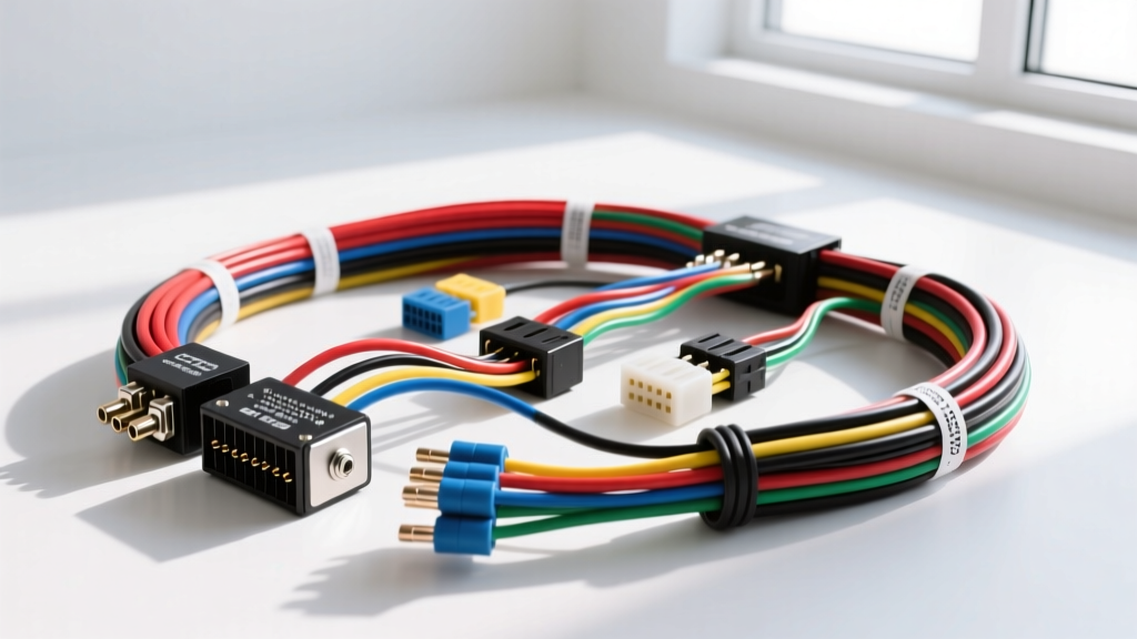
Why OEM GM Color Codes Matter in Aftermarket Swaps
When executing a Gen III or Gen IV LS engine swap into a classic muscle car, import, or off-road chassis, the wiring harness is often the most daunting hurdle. While many builders opt for complete aftermarket harnesses from brands like Painless Performance or Holley, a massive segment of the modification community relies on refurbished OEM GM harnesses. Understanding GM wiring harness color codes is not just about making the right connections; it is critical for integrating OEM gauge clusters, diagnosing faults with factory scan tools, and properly mapping sensors to standalone ECUs like the Holley Terminator X or Megasquirt.
OEM GM harnesses utilize a highly specific, standardized color-coding system governed by internal engineering directives and Helm Incorporated GM Service Manuals. Deviating from these colors during a custom harness extension or repair can lead to catastrophic diagnostic confusion later. This guide breaks down the essential GM color codes, pin configurations, and modification best practices for your upgrade project.
Gen III/IV LS PCM Connector Architecture
The classic Gen III (LS1/LS6) and early Gen IV (LS2/LS3) engines utilize a four-cavity PCM connector setup. Before cutting, splicing, or extending any wires, you must understand the physical layout and the primary color themes associated with each connector cavity.
- C1 (Blue): Primarily handles fuel injector control, cam/crank sensor inputs, and oil pressure.
- C2 (Red): Manages ignition coil control, Idle Air Control (IAC), Throttle Position Sensor (TPS), and Mass Air Flow (MAF).
- C3 (Black): The critical power, ground, and communication hub. Contains main battery feeds, PCM grounds, and the Class 2 Serial Data bus.
- C4 (Gray): Dedicated to O2 sensor monitoring, EVAP purge solenoids, and secondary emissions equipment.
C3 Black Connector: Power, Ground, and Data Pinouts
The C3 Black connector is the lifeline of the PCM. When relocating the PCM to the vehicle cabin—a common modification in tight engine bays like the Mazda Miata or S10 LS swaps—extending the C3 wires requires strict adherence to AWG sizing to prevent voltage drop.
| Pin | Wire Color | Function | AWG Size | Modification Notes |
|---|---|---|---|---|
| 1 | Orange | Constant Battery 12V (Keep Alive Memory) | 14 AWG | Must be fused at 15A. Do not route near coil packs. |
| 2 | Pink | Switched Ignition 12V | 14 AWG | Triggers PCM wake-up. Voltage drop here causes crank/no-start. |
| 16 | Black/White | Main PCM Power Ground | 14 AWG | Must terminate directly to the engine block or clean chassis. |
| 17 | Black/White | Main PCM Sensor Ground | 14 AWG | Do not share this ground path with aftermarket fuel pumps. |
| 58 | Tan | Class 2 Serial Data (ALDL) | 20 AWG | Highly susceptible to EMI. Requires twisted pair routing in custom fab. |
C1 Blue & C2 Red: Injectors and Coils
For modification projects involving port injection upgrades or coil-per-cylinder conversions, knowing the GM injector and coil wire colors is mandatory. GM uses a specific base color with a contrasting tracer for each cylinder to aid in oscilloscope diagnostics.
| Cylinder | Injector Wire (C1 Blue) | Coil Control Wire (C2 Red) | Connector Type |
|---|---|---|---|
| 1 | Pink / Black | White / Black | Metri-Pack 150 |
| 2 | Pink / White | White / Gray | Metri-Pack 150 |
| 3 | Dark Blue / White | White / Yellow | Metri-Pack 150 |
| 4 | Dark Blue / Black | White / Purple | Metri-Pack 150 |
Note: All GM fuel injectors are batch-fire or sequential low-side switched. The opposing side of the injector receives constant 12V (usually Pink) from the main harness relay.
Harness Extension: Moving the PCM to the Cabin
In many upgrade projects, the OEM harness is too short to reach a cabin-mounted PCM, or the engine bay environment is too hostile for the factory plastic loom. Extending a GM harness requires precision. According to the SAE J1128 Low Tension Primary Cable Standard, any replacement wire used in an under-hood environment must feature cross-linked polyethylene (XLPE) or equivalent insulation capable of withstanding 125°C to 150°C continuous heat.
Best Practices for Splicing and Crimping
- Never Use Twist-and-Tape: Capillary action will wick moisture into the copper strands, leading to green rot and high resistance.
- Use OEM-Style Terminals: When extending harnesses through the firewall, utilize Aptiv Metri-Pack 280 series sealed connectors. These provide a weather-tight seal and maintain the OEM pin drag.
- Stagger Your Splices: If you must cut and solder wires in the main loom, stagger the inline butt-splices by at least two inches. This prevents a massive, rigid bulge in the harness that makes pulling it through the firewall grommet impossible.
- Shield the Serial Data Bus: The Tan Class 2 Serial Data wire (Pin 58, C3 Black) operates on a 0-7V square wave. If you extend this wire, wrap it in Tesa cloth tape and route it at least 6 inches away from MSD ignition boxes or coil pack power feeds to prevent U1000 communication codes.
Integrating OEM GM Sensors with Aftermarket ECUs
When adapting an OEM GM harness to an aftermarket ECU like the Holley HP or Megasquirt MS3, retaining the GM wire colors at the sensor pigtails saves immense troubleshooting time. Aftermarket ECU manufacturers map their default pinouts and sensor calibrations directly to GM color codes.
- Coolant Temperature Sensor (CTS): Yellow (Signal) / Black (Ground). GM uses a specific pull-up resistor curve; keeping the OEM pigtail ensures the aftermarket ECU reads the correct temperature without custom calibration tables.
- Intake Air Temperature (IAT): Dark Green (Signal) / Black/White (Ground). Often integrated into the MAF sensor on Gen III harnesses, or standalone in the intake tube on Gen IV setups.
- Throttle Position Sensor (TPS): Dark Blue (Signal) / Black (Ground) / Gray (5V Reference).
Troubleshooting Common Swap Wiring Faults
Even with a perfect understanding of GM wiring harness color codes, modification projects frequently encounter electrical gremlins. Use this decision tree to diagnose common LS swap harness issues:
- Symptom: Cranks but no injector pulse; PCM won't communicate via OBD2.
- Cause: Voltage drop on the Pink (Switched 12V) wire. The PCM sees less than 10.5V during cranking and shuts down non-essential circuits.
- Fix: Check the Pink wire at Pin 2 of the C3 Black connector while cranking. Install a dedicated 30A relay triggered by the ignition switch to feed the Pink wire directly from the battery.
- Symptom: Random U1016 (Lost Communications with PCM) or U1040 codes.
- Cause: The Tan serial data wire is experiencing Electromagnetic Interference (EMI) or shares a poor ground node with the fuel pump.
- Fix: Verify Pin 16 and 17 (Black/White) grounds are sanded to bare metal on the engine block. Reroute the Tan wire away from the alternator output cable.
- Symptom: Engine starts and immediately dies (VATS/Passlock issue).
- Cause: The Yellow/Black VATS wire from the steering column is missing or the PCM still has the factory Vehicle Anti-Theft System enabled.
- Fix: For standalone swaps, use HP Tuners to disable VATS in the PCM software, or wire a 2.2k ohm resistor across the VATS circuit if using a factory BCM.
Final Fabrication Insights
Mastering GM wiring harness color codes transforms a frustrating wiring nightmare into a logical, systematic process. Whether you are building a twin-turbo LS3 for a drift car or dropping a 5.3L into a classic C10, respecting the OEM wire gauges, utilizing proper Metri-Pack terminals, and adhering to SAE insulation standards will ensure your engine swap starts on the first key turn and remains reliable on the track. Always double-reference your specific engine's RPO code (e.g., LS3, LQ4, LM7) against the factory service manual, as minor pinout variations exist between truck (LM7/LQ4) and car (LS1/LS2) harnesses, particularly regarding the VSS (Vehicle Speed Sensor) and neutral safety switch circuits.