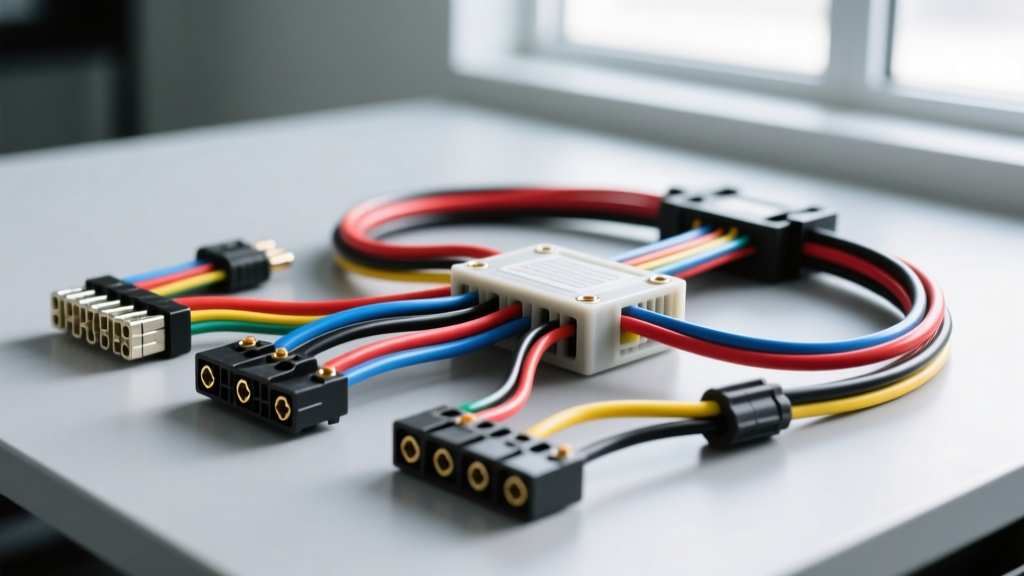
The Hidden Dangers of Universal Kits vs. a Vehicle Specific Wiring Harness
When performing an engine swap or restoring a classic vehicle, the electrical system is often the final—and most frustrating—hurdle. Many builders attempt to save money by using generic, universal wiring kits or piecing together salvaged pigtails. However, failing to utilize a true vehicle specific wiring harness engineered for your exact ECU, sensor suite, and chassis layout is a leading cause of electrical fires, parasitic draws, and catastrophic ECU failure. Universal kits force the installer to guess pinouts, estimate wire lengths, and manually calculate voltage drops, introducing severe safety risks.
This guide details the most critical mistakes made when building or installing engine swap harnesses, with a specific focus on modern EFI conversions like the GM Gen IV (E38/E67) LS/LT platforms. Understanding these safety warnings and adhering to SAE J1128 Low Tension Cable standards will protect your investment and your life.
Mistake #1: Soldering Terminals in High-Vibration Zones
One of the most pervasive myths in automotive wiring is that soldering is superior to crimping. In a static environment, this may be true. In the high-vibration, high-thermal-cycling environment of an engine bay, soldering wire directly into open-barrel crimp terminals (such as Delphi Metri-Pack 2.8 or Weather-Pack connectors) is a severe safety hazard.
The Physics of Solder Failure
- Capillary Action: Liquid solder and flux wick up into the wire strands under heat. This creates a rigid, brittle section of wire just behind the terminal.
- Fatigue Cracking: Engine vibration causes the flexible wire to flex against the rigid soldered section. Over time, the copper strands work-harden and snap, leading to intermittent misfires or total loss of ECU power.
- Flux Corrosion: Acidic flux residues trapped inside the connector housing will corrode the brass or tin-plated copper terminals, increasing resistance and generating excess heat.
The Fix: Always use a calibrated ratcheting crimper designed for open-barrel terminals. The crimp should feature a visible 'bellmouth' at the rear to prevent the wire insulation from being cut by the terminal edges. For environmental sealing, use proper silicone wire seals, never heat-shrink tubing over an open-barrel crimp.
Mistake #2: Undersizing Main Power and Ground Feeds
A modern ECU, such as the GM E38, requires massive transient current to fire multiple ignition coils and high-impedance fuel injectors simultaneously. Relying on the factory 12 AWG or 14 AWG wiring from a donor chassis to feed a swapped ECU is a recipe for severe voltage drop and ECU bricking.
Wire Gauge & Voltage Drop Matrix (10-Foot Run)
| Wire Gauge (AWG) | Max Continuous Amps (SAE J1128) | Voltage Drop @ 15A | Safety Verdict for Main ECU Feed |
|---|---|---|---|
| 14 AWG (TXL) | 15A | 0.77V | DANGER: Fire risk / ECU reset |
| 12 AWG (TXL) | 20A | 0.48V | WARNING: Marginal for coil packs |
| 10 AWG (TXL) | 30A | 0.30V | ACCEPTABLE: Minimum for EFI swaps |
| 8 AWG (TXL) | 40A | 0.19V | IDEAL: Recommended for Gen IV/V |
According to GM Upfitter Integration guidelines, main battery feeds to the ECU and ignition relay banks must utilize a minimum of 10 AWG GXL/TXL wire, with 8 AWG heavily preferred for runs exceeding 8 feet to mitigate voltage drop during cranking.
Mistake #3: The Grounding Fallacy (Using the Chassis as a Return)
Many installers route the main ECU ground wires to the nearest chassis bolt or body panel. Modern ECUs do not use the vehicle chassis as a primary ground return for internal logic or injector drivers; they require dedicated, heavy-gauge grounds routed directly back to the battery negative terminal or the engine block.
Correct Grounding Protocol for LS/LT Swaps
- Engine Block Ground: The main harness ground ring terminal must be secured to a clean, bare metal surface on the cylinder head or block. Use an M8 bolt torqued to 18 lb-ft.
- Surface Prep: Remove all paint, powder coat, and anodizing. Apply a thin layer of conductive anti-seize to prevent galvanic corrosion between the copper terminal and aluminum head.
- ECU Case Ground: Ensure the ECU mounting bracket is grounded to the chassis, but do not rely on this for the main harness ground pins (e.g., E38 Connector X2, Pins 1, 2, 3, and 4).
Mistake #4: Ignoring Shielded Twisted Pair (STP) Requirements for CAN Bus
Modern vehicle specific wiring harness architectures rely heavily on Controller Area Network (CAN) bus communication. Splicing into the OBD2 port to grab CAN-High and CAN-Low signals using standard, untwisted primary wire will result in electromagnetic interference (EMI) from the ignition coils, causing the ECU to drop communication and throw U-codes (e.g., U0100).
CAN Bus Routing Rules
- Twist Rate: CAN-H and CAN-L wires must be twisted together at a rate of 3 to 4 twists per inch to cancel out electromagnetic noise.
- Termination: The CAN bus requires a 120-ohm resistor at each physical end of the network. Most modern ECUs have this built-in, but if you are integrating aftermarket dashes, you must verify total bus resistance is between 60 and 70 ohms with a multimeter.
- Clearance: Never route CAN bus wiring parallel to high-voltage ignition coil feeds. If they must cross, they must do so at a strict 90-degree angle.
Safety Warning Matrix: Symptoms of Harness Abuse
| Observed Symptom | Root Cause (Harness Mistake) | Corrective Action |
|---|---|---|
| ECU resets during engine cranking | Voltage drop on main ECU power feed due to undersized wire (12 AWG or smaller). | Upgrade main relay-to-ECU power feed to 8 AWG TXL wire. |
| Random injector misfires at high RPM | Wire strands fatigued and broken due to solder wicking in the injector pigtail. | Cut out soldered pigtails; crimp new Metri-Pack 2.8 terminals with proper seals. |
| Erratic TPS / MAF sensor readings | Sensor ground shared with a high-amperage component (ground loop noise). | Run dedicated 18 AWG sensor ground wires directly to the ECU sensor ground pin. |
| Melted insulation near exhaust headers | Harness routed within 4 inches of exhaust without proper thermal protection. | Reroute harness. Apply silicone-coated fiberglass heat sleeving rated to 1200°F. |
Best Practices for Routing and Firewall Penetration
Even a perfectly pinned vehicle specific wiring harness will fail if the physical routing is compromised. The transition from the engine bay to the cabin is a critical failure point.
- Firewall Grommets: Never pass wires through bare sheet metal. Use a stepped rubber firewall grommet. Apply dielectric grease to the wires before pushing them through to prevent the rubber from binding and tearing the wire insulation.
- Drip Loops: Before entering any connector, bulkhead, or cabin grommet, form a 'drip loop' in the harness. This ensures that water running down the wires drips off the lowest point of the loop rather than being funneled directly into the connector housing, preventing terminal oxidation.
- Looming Materials: Avoid cheap, corrugated plastic split-loom in the engine bay; it degrades under UV and heat exposure, becoming brittle and slicing into wire insulation. Instead, use TESA 51036 PET cloth tape or woven nylon braided sleeving for engine bay harness wrapping, as mandated by OEM automotive standards.
Conclusion: Invest in Specificity
Electrical faults are the number one cause of trailered race cars and abandoned project builds. By abandoning universal kits in favor of a high-quality, vehicle specific wiring harness, and by strictly adhering to SAE crimping, grounding, and routing standards, you ensure that your vehicle's nervous system operates safely and reliably for decades. Never compromise on wire gauge, terminal crimp quality, or CAN bus topology.