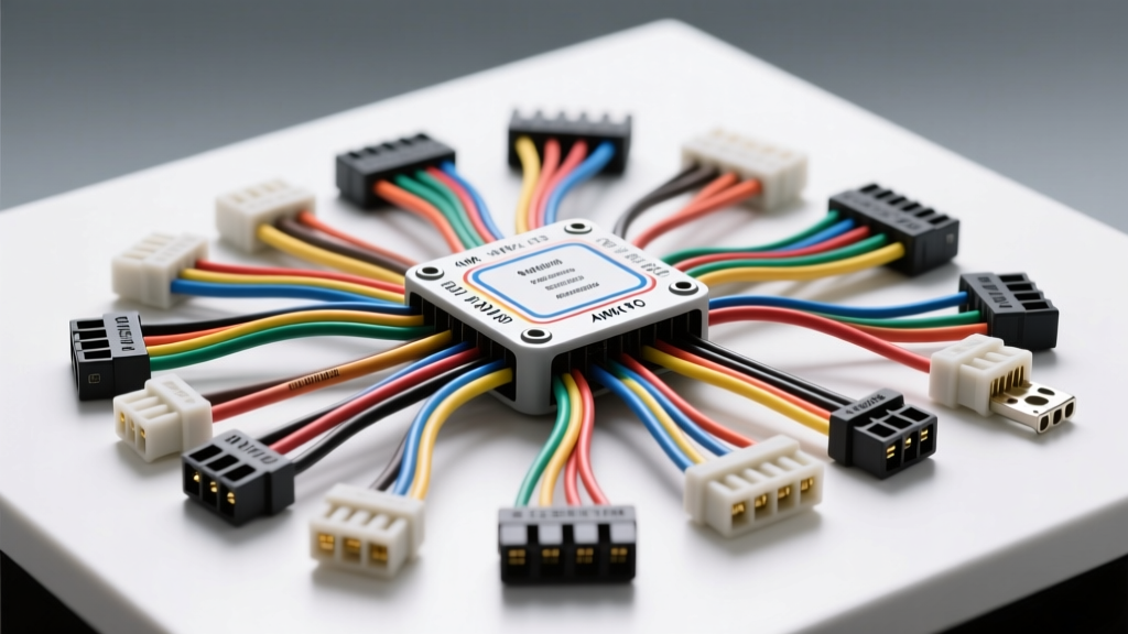
The Evolution of Dedicated Wiring Harness Design Software
The complexity of modern automotive electrical systems has rendered generic 2D CAD tools insufficient for custom builds, engine swaps, and OEM replacement harness fabrication. Dedicated wiring harness design software bridges the critical gap between logical electrical schematics and physical manufacturing. Unlike standard electrical drafting tools, specialized harness software utilizes a topology-first approach. This means the software understands the physical properties of the wire, the exact cavity assignments of the connectors, and the precise routing paths required to generate accurate formboards (nail boards) and cut lists. For automotive electrical experts building anything from a basic headlight relay kit to a complete aftermarket LS-swap engine harness, leveraging the right software is essential for minimizing voltage drop, ensuring proper IPC/WHMA-A-620 crimp standards, and generating flawless Bills of Materials (BOM).
Core Technical Requirements for Automotive Harness Software
Wire Gauge (AWG) and Voltage Drop Calculations
One of the primary advantages of dedicated harness software is automated voltage drop calculation based on real-world physics. When designing a high-current circuit, such as a fuel pump relay feed, the software calculates the required American Wire Gauge (AWG) based on the total wire length, the ambient temperature rating of the insulation, and the maximum continuous amperage. For example, routing a 15-amp fuel pump circuit over a 14-foot run requires a minimum of 10 AWG (5.0 mm²) wire to maintain a voltage drop below 0.5 volts at the load. Advanced software platforms automatically flag voltage drop violations if a designer attempts to assign an 18 AWG (0.8 mm²) sensor wire to a 10-amp circuit, preventing catastrophic thermal failures before the harness is ever built.
Connector and Pinout Database Management
Automotive harnesses rely on highly specific sealed and unsealed connectors. A robust wiring harness design software includes extensive, updatable component libraries for manufacturers like TE Connectivity, Molex, and Deutsch. The software must recognize that a TE Connectivity Superseal 1.5 series 2-way connector (Part #282087-1) requires specific silicone cavity plugs and wire seals based on the insulation diameter of the chosen wire. Furthermore, the software tracks mating halves, ensuring that a 12-way Deutsch DTM receptacle (DTM04-12P) is correctly mated to the corresponding DTM06-12S plug, automatically generating the correct wedge locks and secondary retention mechanisms in the BOM.
Top Wiring Harness Design Software Platforms Compared
| Software Platform | Best Automotive Use Case | Topology & Formboard | 3D CAD Integration | BOM & Splice Accuracy |
|---|---|---|---|---|
| Siemens Capital Harness | OEM & High-Volume Aftermarket | Advanced 2D/3D Formboard | Native NX / Solid Edge | Enterprise-Grade |
| Zuken E3.series | Complex Motorsport & EV Swaps | Dynamic Nail Board Generation | CATIA / Creo / SolidWorks | High Precision |
| Cadonix RapidHarness | Custom 1-Off Builds & Restomods | Cloud-Based Formboard | STEP File Import | Excellent for Small Shops |
| Arcadia Harness | Wire-Only Logic & Schematic Capture | Basic 2D Routing | Limited | Moderate |
SAE Standards and Material Specifications in Digital Design
Professional harness design software integrates material databases governed by the SAE J1128 standard for low-tension primary automotive cable. The software allows designers to specify not just the AWG, but the exact insulation chemistry and wall thickness, which directly impacts the harness's flexibility, weight, and temperature resistance.
- TXL (Thin Wall Cross-Linked): Rated for 125°C. Features the thinnest insulation wall, making it ideal for tight routing inside the cabin, under-dash clusters, and modern CAN-bus networks where bundle diameter must be minimized.
- GXL (General Purpose Cross-Linked): Rated for 125°C. The industry standard for engine bay routing. It offers a balance of flexibility and mechanical abrasion resistance against chassis brackets and firewall grommets.
- SXL (Special Cross-Linked): Rated for 150°C. Features the thickest insulation. Software will automatically suggest SXL for circuits routed near exhaust manifolds, turbocharger downpipes, or EGR systems where ambient under-hood temperatures exceed standard thresholds.
By defining these materials in the software, the generated cut list will accurately reflect the different stripping lengths required for TXL versus SXL wires, ensuring the automated wire stripping machines or manual technicians achieve the perfect bellmouth crimp profile.
Practical Workflow: Designing an LS-Swap Engine Harness
To understand the practical application of wiring harness design software, consider the workflow for designing a custom harness for a Gen IV LS engine swap utilizing an E38 or E40 ECM. The logical schematic capture begins with defining the ECM connectors: X1 (Black, 38-way), X2 (Gray, 38-way), and X3 (Brown, 38-way).
Step 1: Topology and Schematic Capture
The designer assigns specific circuits to the software. For example, Pin A1 on the X1 connector is designated as Ignition 12V Switched, requiring a 14 AWG GXL Red wire routed to the ignition switch relay. Pin B1 is designated as ECM Ground, requiring a heavy 8 AWG Black wire routed directly to the cylinder head ground stud. For the 58x reluctor wheel camshaft and crankshaft position sensors, the software assigns 18 AWG TXL shielded twisted pair (STP) wire to prevent electromagnetic interference (EMI) from the high-voltage ignition coils. The software automatically calculates the required shield drain wire routing to a clean chassis ground.
Step 2: Splice Management and Formboard Generation
Engine harnesses require numerous splices to distribute power and ground. Instead of messy solder joints, the software specifies ultrasonic or staggered barrel splices sealed with dual-wall adhesive heat shrink. The software generates a 1:1 scale digital formboard (nail board) drawing. This drawing dictates the exact physical placement of every connector, breakout point, and splice. The technician builds the harness flat on the board, ensuring that the branch lengths to the MAF sensor, MAP sensor, and electronic throttle body (ETB) are perfectly matched to the physical engine dimensions, preventing tension on the TE/Molex connector terminals.
Harness Documentation and Manufacturing Outputs
The final output of wiring harness design software extends far beyond a simple drawing. The software generates comprehensive manufacturing documentation, including a wire cut-list sorted by color and gauge, a terminal crimp matrix specifying the exact tooling dies (e.g., Molex MX150 specific crimp profiles), and a continuity test sequence for bench testing. By utilizing dedicated wiring harness design software, automotive electrical engineers and custom fabricators ensure that every harness produced meets rigorous OEM-level reliability standards, eliminating the guesswork and reducing the risk of electrical fires or intermittent sensor faults in high-performance applications.