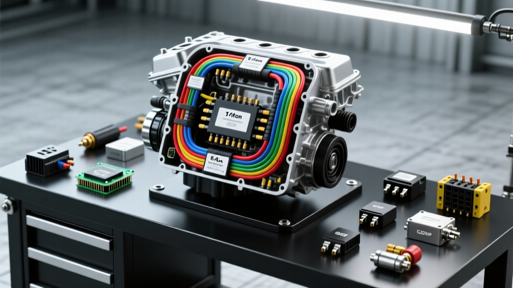
Decoding the 5.4 Triton Wiring Harness Diagram for Engine Swaps
Swapping the Ford 5.4L Triton Modular V8 into a classic F-100, early Bronco, or custom hot rod is a popular upgrade project that delivers massive torque and modern reliability. However, the factory 5.4 Triton wiring harness diagram is notoriously complex, packed with emissions circuitry, PATS (Passive Anti-Theft System) immobilizer loops, and fragile Coil-On-Plug (COP) wiring. When executing a standalone swap or upgrading an existing Triton for forced induction, relying on the stock harness without modification is a recipe for parasitic draws, melted insulation, and catastrophic misfires.
This comprehensive guide breaks down the critical circuits of the 5.4L 2-valve and 3-valve Triton harnesses. We will cover PCM pinout strategies, high-temperature wire upgrades, PATS integration, and the specific grounding protocols required to keep the Modular V8 firing perfectly under heavy loads. Whether you are building a custom harness from scratch or modifying an OEM donor harness, understanding the underlying architecture of the Triton electrical system is mandatory.
Core PCM Connector Pinouts and VPWR Circuits
The brain of the 5.4L Triton is the Powertrain Control Module (PCM). Depending on the year, you will be dealing with either a 104-pin (early 2V) or a 112-pin (late 3V) connector. The most critical circuit to map during a swap is the VPWR (Vehicle Power) circuit. Unlike older pushrod engines that used a simple 12V ignition feed, the Triton PCM requires multiple dedicated, fused 12V feeds to power the internal logic, injector drivers, and COP transformers.
| PCM Pin (104-Pin) | Circuit Function | Wire Color (Typical) | AWG Size | Swap Action |
|---|---|---|---|---|
| 13, 14, 15, 16 | VPWR (Main Relay Feed) | Light Green/Purple | 14 AWG | Connect to fused 12V ignition source (min 30A) |
| 25, 51, 77, 103 | PCM Power Ground | Black/White | 16 AWG | Must ground directly to engine block, not chassis |
| 71, 72 | Keep Alive Memory (KAM) | Light Green/Purple | 18 AWG | Connect to constant 12V battery feed (min 10A) |
| 85, 86, 87 | Injector Bank 1 Power | Red/Light Green | 16 AWG | Fused 12V feed for high-impedance injectors |
| 58, 59, 83, 84 | COP Power Feed | Red/Light Green | 14 AWG | Requires dedicated 30A relay for 8 coils |
Note: Always verify wire colors against your specific year's Motorcraft technical resources and EVTM (Electrical and Vacuum Troubleshooting Manual), as Ford frequently updated tracer colors between 1997 and 2010.
Upgrading the Coil-On-Plug (COP) Harness
The most common failure point in any 5.4 Triton wiring harness diagram is the COP secondary harness. The factory harness uses standard 18 AWG PVC-insulated wire routed dangerously close to the exhaust manifolds. In a swap application, where engine bay clearances are tight and under-hood temperatures spike, this factory wiring will melt, short out, and cause random P0300-P0308 misfire codes.
Step-by-Step COP Harness Fabrication
- Strip the Factory Loom: Carefully remove the corrugated plastic split-loom and factory tape from the COP pigtails.
- Upgrade Wire Gauge: Replace the factory 18 AWG wires with SAE J1128 compliant 16 AWG TXL (Cross-Linked Polyethylene) wire. TXL wire is rated for continuous 125°C operation and features a thin, highly abrasion-resistant insulation.
- Solder and Seal: Solder the new 16 AWG TXL wire to the factory COP connector pins using rosin-core solder. Seal the splice with dual-wall heat shrink tubing featuring an inner polyamide adhesive lining to prevent moisture ingress.
- Reroute Away from Heat: Route the upgraded COP harness along the inner fender wells or valve cover rails, maintaining a minimum 3-inch clearance from the exhaust headers. Use high-temperature fiberglass sleeving (rated to 1000°F) over the harness sections that must cross near exhaust components.
PATS (Passive Anti-Theft System) Integration and Bypass
No 5.4 Triton swap project is complete without addressing the PATS immobilizer. The PCM will disable the fuel injectors and starter relay if it does not detect the correct RFID chip in the ignition key. For a standalone harness project, you have two options: integrate the factory PATS transceiver or use a standalone EFI system/PATS delete tune.
If you are retaining the Ford PCM and integrating the PATS transceiver ring around your custom ignition cylinder, you must wire the 4-pin transceiver connector correctly:
- Pin 1 (TX - Transmit): Pink/Light Blue wire to PCM Pin 92.
- Pin 2 (RX - Receive): White/Light Green wire to PCM Pin 93.
- Pin 3 (VPWR): Red/Light Green wire to a switched 12V source.
- Pin 4 (Ground): Black/White wire to a clean chassis ground.
Failure to twist the TX and RX wires together (at least 2 twists per inch) will result in electromagnetic interference (EMI) from the COP transformers, causing the PCM to misread the key transponder and immobilize the engine.
Fuel Injector Harness Modifications for High-Flow Upgrades
When upgrading a naturally aspirated 5.4L to a supercharged or turbocharged setup, the factory 19 lb/hr injectors are typically swapped for 60 lb/hr or larger units. The factory injector harness uses 20 AWG wire, which is sufficient for the low-current draw of stock high-impedance injectors. However, if your upgrade project utilizes low-impedance injectors (common in high-horsepower applications), the factory wiring and PCM drivers will overheat and fail.
For low-impedance injector upgrades, you must install inline ballast resistors (typically 4.7 to 6.8 ohms, 25-watt ceramic) on the 12V VPWR feed side of each injector. Alternatively, upgrade the entire injector harness to 16 AWG TXL wire and utilize an aftermarket standalone ECU (such as those detailed in Holley EFI swap documentation) that features peak-and-hold injector drivers capable of handling the higher current safely without external resistors.
3V VCT Solenoid Wiring for Advanced Swaps
If your upgrade project utilizes the more advanced 5.4L 3-valve engine (2004-2010), your wiring harness diagram must include circuits for the Variable Cam Timing (VCT) solenoids. The 3V engine uses oil pressure to advance the camshafts, controlled by two PWM (Pulse Width Modulated) solenoids located on the front of the cylinder heads.
Each VCT solenoid requires a dedicated 12V VPWR feed (shared with the COP circuit) and a dedicated PCM-controlled ground. The PCM ground wires (typically White/Red for Bank 1 and White/Blue for Bank 2) must be shielded. Because the VCT solenoids draw up to 1.5 amps during peak actuation, voltage drop across undersized wires will result in sluggish cam phasing, poor idle quality, and P0012/P0022 over-retarded cam timing codes. Ensure the VCT ground wires are a minimum of 18 AWG and routed away from the alternator output cable.
The Modular Block Grounding Strategy
The 5.4L Triton features an aluminum block and aluminum cylinder heads. Aluminum is highly susceptible to galvanic corrosion, which rapidly increases electrical resistance at grounding points. A poor ground on a Triton swap will cause the COP system to seek a ground through the throttle body cable or alternator bracket, resulting in severe alternator whine in the audio system and erratic TPS (Throttle Position Sensor) voltage readings.
Implement this mandatory grounding tree for your swap harness:
- Main Engine Ground: Run a 4 AWG or 2 AWG copper cable from the negative battery terminal directly to a clean, bare-metal pad on the passenger side cylinder head or engine block lifting eye.
- Block-to-Chassis Ground: Run a 4 AWG strap from the rear of the engine block (near the bellhousing) to the vehicle chassis or frame rail.
- Head-to-Firewall Ground: Install a 10 AWG braided copper strap from the driver-side cylinder head to the firewall. This provides a clean ground path for the PCM sensors and prevents EMI from entering the cabin.
- PCM Sensor Grounds: The PCM pins 25, 51, 77, and 103 must be grounded directly to the engine block using a dedicated ground ring terminal, completely isolated from the main high-amperage engine grounds to prevent voltage ripple from corrupting the MAF and O2 sensor signals.
Troubleshooting Common Triton Harness Failures
Even with a meticulously built harness, swap projects can encounter electrical gremlins. Use this decision tree to diagnose common 5.4L wiring issues:
| Symptom | Probable Electrical Cause | Diagnostic Fix |
|---|---|---|
| Random Misfires (P0300) under boost/load | Voltage drop in COP VPWR circuit due to undersized wire or corroded relay contacts. | Measure voltage at COP connector under load. If below 11.5V, upgrade VPWR feed to 12 AWG and install a heavy-duty 40A Bosch-style relay. |
| Erratic Idle / Surging | TPS or IAC signal wire picking up EMI from unshielded COP secondary wires. | Reroute TPS/IAC harness minimum 4 inches from COP wires. Verify PCM sensor grounds are not shared with high-current accessories. |
| Engine Cranks but No Start (Injectors silent) | PATS immobilizer active, or CCRM (Constant Control Relay Module) fuel pump relay failure. | Check for flashing theft light. Verify 12V at injector VPWR pins during cranking. Check CCRM ground circuit. |
| Alternator Whine in Stereo | Missing head-to-firewall ground strap or alternator case ground failure. | Install 10 AWG braided ground strap from alternator case to engine block, and head to firewall. |
Final Harness Looming and Protection
Once all circuits are tested, pinned, and verified, the final step is protecting your custom 5.4 Triton wiring harness. Avoid using standard corrugated plastic split-loom in the engine bay, as it traps moisture and degrades under high heat. Instead, wrap the entire harness in Tesa 51036 PET (Polyethylene Terephthalate) cloth tape. This tape is abrasion-resistant, withstands continuous temperatures up to 150°C, and provides a clean, OEM-style finish that flexes with engine movement without cracking or unraveling. For sections passing through the firewall or near sharp metal brackets, slide a piece of self-closing braided fiberglass sleeving over the PET tape for ultimate mechanical protection.