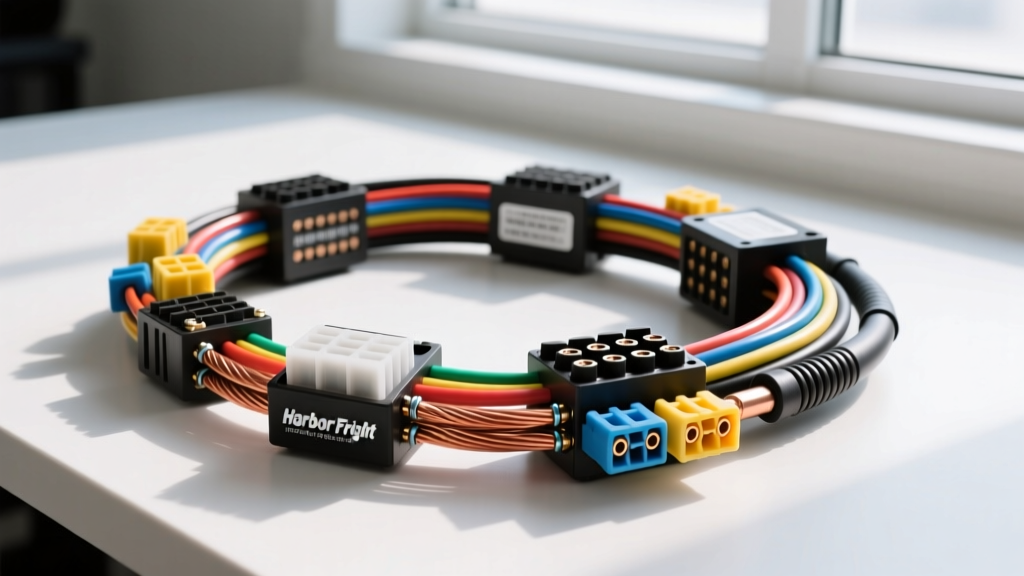
The Reality of Budget Harness Kits in Automotive Projects
When building a custom off-road trailer, expedition rig, or budget motorcycle hauler, the harbor freight wiring harness is a frequent starting point. These generic 4-way flat and 7-way RV kits are inexpensive and readily available, making them attractive for quick modifications. However, from an automotive electrical engineering perspective, these budget harnesses present severe limitations. They typically utilize Copper-Clad Aluminum (CCA) wire, non-sealed molded connectors, and PVC insulation that becomes brittle under UV exposure and high engine-bay temperatures.
For a true upgrade and modification project, we do not simply install the stock harness and hope for the best. Instead, we use the budget harness as a foundational trigger system, stripping out the high-current pathways and upgrading the architecture to handle heavy-duty auxiliary lighting, electric winches, and trailer brakes. This guide details how to transform a standard off-the-shelf kit into a professional-grade, weather-sealed wiring system capable of surviving extreme off-road environments.
Evaluating the Stock Harness vs. Heavy-Duty Upgrades
Before cutting a single wire, it is critical to understand the material science differences between budget retail kits and OEM-grade automotive wiring. According to SAE J1128 standards, automotive wire must withstand specific thermal and chemical abrasion thresholds. Budget kits rarely meet these criteria.
| Specification | Stock Budget Harness | Heavy-Duty Upgrade |
|---|---|---|
| Wire Conductor | 18 AWG CCA (Copper-Clad Aluminum) | 12 AWG & 16 AWG Pure Copper (TXL/GXL) |
| Insulation Material | PVC (Melts at 105°C, UV degrades) | XLPE (Cross-linked, rated to 125°C+) |
| Connectors | Molded Rubber 4-Way Flat | Sealed Weather-Pack or Deutsch DT Series |
| Max Continuous Load | ~6 Amps (High Voltage Drop over 10ft) | 40+ Amps (Relay-switched power) |
Step-by-Step Heavy-Duty Harness Modification
Phase 1: Stripping the Weak Links and Upgrading the Ground
The most common failure point in any trailer or auxiliary harness is the ground. The stock 18 AWG white ground wire in a budget harness will bottleneck your entire electrical system, causing voltage drop, dim lights, and back-feeding through the tail light circuits.
The Fix: Cut the white ground wire completely off at the molded connector. Replace it with a 10 AWG pure copper wire terminated with a heavy-duty, adhesive-lined heat-shrink ring terminal. Bolt this directly to a clean, bare-metal point on the trailer chassis or vehicle frame. Use a star washer to bite through paint and prevent galvanic corrosion. The ground path must always be equal to or larger than the main power feed.
Phase 2: Integrating ISO Relays for High-Draw Aux Lights
If you are using the harness to power off-road LED light bars or trailer floodlights, you cannot run the load through the thin 18 AWG CCA wires. Doing so will cause the wires to act as resistors, generating excessive heat and potentially causing a fire. Instead, we convert the budget harness into a trigger-only system using standard ISO mini relays (Bosch-style).
By utilizing a relay, the high-current draw bypasses the fragile harness entirely. The budget harness merely signals the relay to close the high-amperage circuit. Refer to Littelfuse automotive relay specifications for exact ISO 7588 pinout tolerances.
- Pin 30 (Power In): Run 12 AWG TXL wire directly from the vehicle battery positive terminal, through a 30A ATC fuse holder, to Pin 30.
- Pin 87 (Power Out): Run 12 AWG wire from Pin 87 to your auxiliary lights or trailer power distribution block.
- Pin 86 (Trigger In): Splice into the budget harness's running light wire (Brown) or turn signal wire (Yellow/Green) using a 16 AWG tap. This provides the 12V+ signal to energize the relay coil.
- Pin 85 (Ground): Connect to a dedicated chassis ground using 16 AWG wire.
Phase 3: Upgrading to Sealed Connectors
The molded 4-way flat connector is notorious for trapping moisture and suffering from pin corrosion. For an expedition or off-road build, moisture ingress is guaranteed. We recommend cutting off the molded end and installing a sealed connector system. The TE Connectivity Weather-Pack series or Deutsch DT connectors feature silicone seals that prevent water from wicking into the wire crimps.
Crimping Protocol: Never use standard pliers for sealed connectors. You must use a ratcheting crimp tool with the correct die for Weather-Pack terminals. The wire crimp and the insulation crimp must be distinct. After crimping, slide a piece of dual-wall adhesive heat shrink over the wire barrel and apply heat until the inner adhesive oozes out, creating a watertight seal before inserting the terminal into the connector housing.
Wiring Diagram & Pinout Reference for Relay Integration
When modifying the harness to trigger a 4-pin relay for an auxiliary trailer work-light circuit, follow this color-code and pinout matrix to maintain consistency with automotive standards:
| Relay Pin | Function | Wire Color (Upgrade) | Wire Gauge | Connection Point |
|---|---|---|---|---|
| 85 | Coil Ground | Black | 16 AWG | Chassis Ground / Battery (-) |
| 86 | Coil Trigger (+) | Red | 16 AWG | Spliced to Harness Brown (Tail) Wire |
| 30 | Switched Power In | Red (w/ Inline Fuse) | 12 AWG | Battery (+) via 30A Fuse |
| 87 | Switched Power Out | Blue | 12 AWG | Auxiliary Light (+) / Trailer Feed |
Common Failure Modes and Troubleshooting
Even with upgrades, modified budget harnesses can present unique diagnostic challenges. Use this decision tree to troubleshoot common issues encountered during modification projects:
- Symptom: Auxiliary lights flicker when the turn signal is activated.
Cause: Back-feeding through the budget harness ground.
Fix: The 10 AWG ground upgrade was not completed, or the ground point shares a circuit with the turn signals. Move the main ground to a dedicated, isolated steel bolt on the chassis. - Symptom: Relay clicks, but no power reaches Pin 87.
Cause: Voltage drop on the trigger circuit failing to fully close the relay contacts.
Fix: Check the CCA trigger wire (Pin 86). CCA wire suffers from severe voltage drop over distance. Replace the trigger wire with pure 16 AWG copper, or move the relay closer to the battery and the trigger source. - Symptom: Heat shrink is melting near the connector.
Cause: Routing the upgraded 12 AWG power feed too close to the exhaust or using PVC wire instead of TXL.
Fix: Reroute the harness utilizing split-loom tubing and high-temp reflective tape. Ensure all replacement wire meets SAE J1128 GXL/TXL temperature ratings.
Conclusion
A harbor freight wiring harness does not have to be a liability in your off-road or custom automotive project. By recognizing its limitations—specifically the use of CCA wire and unsealed connectors—you can strategically modify the kit. Stripping out the high-current pathways, integrating ISO relays, and terminating the system with sealed Weather-Pack connectors transforms a fragile budget part into a robust, expedition-ready electrical backbone. Always prioritize pure copper conductors, proper ratcheting crimps, and dedicated grounding to ensure your auxiliary systems perform flawlessly in the harshest environments.