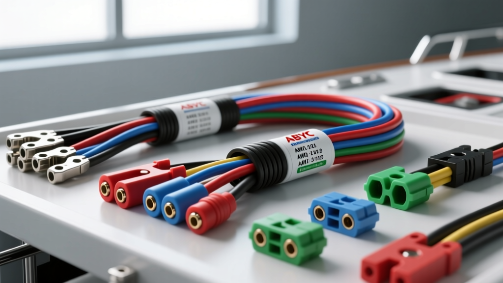
Marine vs. Automotive: Why ABYC Standards Dictate Boat Wiring Harness Replacement
When executing a boat wiring harness replacement, treating the marine electrical system like a standard automotive application is a critical error that inevitably leads to galvanic corrosion, voltage drop, and catastrophic electrical fires. While automotive systems rely on SAE J1128 standards, marine environments demand strict adherence to the American Boat and Yacht Council (ABYC) E-11 standards. The saltwater environment, constant vibration, and high-humidity bilge areas necessitate specialized materials, specific wire stranding, and rigorous routing protocols.
This technical specification reference provides the exact AWG sizing, ABYC color codes, connector pinouts, and torque specifications required for a compliant and reliable boat wiring harness replacement, whether you are rewiring a center console outboard rigging harness or replacing a stern drive instrumentation loom.
Wire Construction: UL 1426 vs. SAE J1128
Automotive wire (SAE J1128) utilizes untinned copper. In a marine environment, untinned copper rapidly oxidizes, forming cupric oxide—a black, powdery substance that acts as a resistor, generating heat and causing voltage drop. For any boat wiring harness replacement, you must use marine-grade wire rated to UL 1426. This wire features individually tinned copper strands to prevent capillary action wicking of moisture and resists corrosion.
- Stranding: Use Type 3 (fine) or Type 6 (extra fine) stranding. A 10 AWG marine wire should have a minimum of 65/30 stranding (65 strands of 30 AWG wire) to withstand the constant high-frequency vibration of outboard engines and hull impacts.
- Insulation: PVC insulation must be rated for 105°C in dry locations and 60°C in wet locations (bilges). It must also resist battery acid, oil, and UV exposure.
AWG Sizing and Voltage Drop Specifications
Unlike automotive applications where wire runs are relatively short, boats feature extended cable runs from the helm to the transom or bow. Sizing wire solely based on ampacity is dangerous; you must size for maximum allowable voltage drop. ABYC E-11 mandates a maximum 3% voltage drop for navigation and electronics, and a 10% drop for non-critical loads (e.g., bait pumps, cabin lighting).
The formula for calculating voltage drop in a 12V DC marine system is: VD = (2 x L x I x r) / 1000, where L is the total round-trip length in feet, I is current in amps, and r is the resistance per 1000 ft of the specific AWG.
| AWG Size | Max Amps (Engine Room)* | Max Amps (Outside Engine Room) | Ohms per 1000 ft (Copper @ 77°F) |
|---|---|---|---|
| 16 AWG | Not Permitted | 10A | 4.09 |
| 14 AWG | Not Permitted | 15A | 2.57 |
| 12 AWG | 15A | 20A | 1.62 |
| 10 AWG | 20A | 30A | 1.02 |
| 8 AWG | 30A | 50A | 0.64 |
| 6 AWG | 40A | 70A | 0.40 |
| 4 AWG | 60A | 100A | 0.25 |
*Note: Ampacity derating is required when wires are bundled in a harness or routed through engine compartments due to ambient heat.
ABYC E-11 Marine Wire Color Code Reference
Standardizing wire colors is critical for future troubleshooting and emergency repairs at sea. Never use automotive color conventions (where black is ground) without verifying the marine standard, as black in marine DC systems can sometimes denote the positive feed for specific 24V setups, though Yellow is now the preferred DC negative.
| Wire Color | Function / Circuit Identification |
|---|---|
| Red | DC Positive (Main unswitched power, battery to switch) |
| Black or Yellow | DC Negative (Ground return, battery negative bus) |
| Dark Blue | Navigation and Anchor Lights |
| Brown | Bilge Blower, Stereo Memory, General Accessories |
| Light Blue | Oil Pressure Gauge / Sender Feed |
| White | Instrument Panel Feed, Common Ground for Gauges |
| Green | DC Grounding (Bonding system, NOT for current carrying) |
| Yellow/Red Stripe | Starting Motor Solenoid Feed (Ignition switch to starter) |
Marine Connector Specifications and Pin Configurations
Twist-on wire connectors and standard automotive butt splices are strictly prohibited by ABYC. All connections in a boat wiring harness replacement must be made using ratcheting crimp tools and marine-grade, adhesive-lined heat shrink terminals (e.g., 3M FP-301 or Ancor). For multi-pin harness connections between the helm and outboard engine, sealed connector systems are mandatory.
Deutsch DT Series (Outboard Engine Harnesses)
The Deutsch DT series is the industry standard for outboard rigging harnesses, offering IP69K waterproofing and high-vibration resistance.
- Connector Types: DT04-2P (2-Pin Receptacle/Housing), DT06-2S (2-Pin Plug).
- Pin Crimp Spec: Use solid copper barrel crimps. The wire insulation grip must crimp the jacket, while the wire grip crimps the tinned strands. Pull-test requirement: 40 lbs for 16-14 AWG.
- Sealing: Requires insertion of the orange silicone wedge lock (W2P or W2S) to splay the contacts and seal the rear wire entry points against moisture ingress.
AMP Superseal 1.5 Series (Instrumentation & Sensors)
Commonly used for pitot tubes, temperature senders, and NMEA 0183 GPS connections.
- Pin Configuration: Male tab (0.157" width) mates with female receptacle.
- Wire Range: Optimized for 18 to 20 AWG wire.
- Dielectric Grease: Always pack the mating face with marine dielectric grease (e.g., Nyogel 760G) to prevent galvanic corrosion between the brass/phosphor-bronze pins.
Step-by-Step Boat Wiring Harness Replacement Procedure
- Isolate Power: Disconnect the negative battery cable first, followed by the positive. Lock out the battery switch to prevent accidental engagement.
- Map and Label: Before removing the old harness, use a tone generator and probe to trace circuits through the helm. Label every wire with heat-shrink printed markers (avoid masking tape, which degrades in UV and humidity).
- Extract Old Loom: Carefully cut zip ties. Inspect the routing path for sharp fiberglass edges or aluminum burrs that may have caused the original harness failure.
- Prep the Routing Path: Install split-loom corrugated tubing (nylon, UV resistant) over the new harness. Apply anti-chafe tape (e.g., 3M Temflex) anywhere the harness passes through a bulkhead or metal stringer.
- Secure the Harness: ABYC E-11 requires harness support every 18 inches (450mm). Use UV-stabilized nylon cable clamps with stainless steel screws. Never use staple guns or metal zip ties, which can slice insulation and cause short circuits.
- Terminate and Torque: Crimp ring terminals using a calibrated ratcheting tool. Apply a thin layer of antioxidant compound (e.g., NO-OX-ID A-Special) to battery studs and bus bars. Torque 3/8" battery terminal nuts to 120 in-lbs (10 ft-lbs) and 5/16" nuts to 80 in-lbs.
- Continuity and Drop Test: Before applying power, use a multimeter to check for dead shorts between the positive bus and the hull ground. Reconnect power and measure voltage drop across the new harness under full load.
Diagnostic Matrix: Common Harness Failure Modes
| Symptom | Probable Cause | Technical Fix / Verification |
|---|---|---|
| Black, powdery residue under wire insulation near terminals. | Capillary wicking of moisture into untinned copper strands (galvanic corrosion). | Cut wire back to bright copper. Replace with UL 1426 tinned marine wire. Use adhesive-lined heat shrink. |
| Navigation lights flicker or dim when bow thruster engages. | Undersized wire gauge causing >3% voltage drop; shared ground bus overload. | Upsize navigation feed by 2 AWG sizes. Run dedicated negative return to main bus (avoid daisy-chain grounds). |
| Outboard tilt/trim relay clicks rapidly but motor does not move. | High resistance in the harness ground path or corroded Deutsch DT pins. | Perform voltage drop test on the negative circuit while under load. Clean pins with electrical contact cleaner and apply dielectric grease. |
| Melted wire insulation near the engine harness grommet. | Chafing against aluminum transom bracket causing intermittent short to ground. | Install rubber grommet or anti-chafe UHMW tape. Verify inline circuit breaker is sized correctly (e.g., 40A for 8 AWG). |