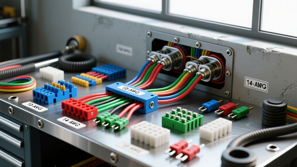
Why a 14 Circuit Wiring Harness Fits Your Resto-Mod
When stripping down a classic street rod or resto-mod project, the factory electrical system is rarely worth saving. Decades of heat cycling, brittle PVC insulation, and outdated glass-tube fuses present a severe fire hazard and limit your ability to run modern accessories. However, jumping straight to a massive 24-circuit or 30-circuit universal kit often results in a tangled rat's nest of unused wires behind the dash. A 14 circuit wiring harness represents the optimal middle ground for traditional hot rods, muscle cars, and custom buggies. It provides dedicated, fused channels for essential modern upgrades—like electric cooling fans, electronic fuel injection (EFI) relays, and halogen lighting—without the bloat of circuits designed for power windows, power seats, or complex HVAC systems found in modern luxury cruisers.
Circuit Breakdown: Mapping the 14 Channels
Properly mapping your 14 circuit wiring harness to the vehicle's specific load requirements is critical to preventing voltage drop and blown fuses. The following specification chart outlines the standard channel allocation, recommended American Wire Gauge (AWG) sizing, and ATO/ATC blade fuse ratings based on SAE J1128 Low Tension Primary Cable Standards.
| Circuit | Function | AWG Size | Fuse Rating | SAE Wire Color |
|---|---|---|---|---|
| 1 | Headlights (High/Low) | 12 AWG | 20A | Dark Blue / Light Green |
| 2 | Taillights & Markers | 14 AWG | 10A | Brown |
| 3 | Dash Illumination | 16 AWG | 5A | White |
| 4 | Wipers | 14 AWG | 10A | Black/Pink Tracer |
| 5 | Horn | 12 AWG | 20A | Yellow |
| 6 | Heater/AC Blower | 14 AWG | 15A | Orange |
| 7 | Ignition Switch Main | 10 AWG | 30A | Pink |
| 8 | Accessory 1 (EFI/Fuel Pump) | 12 AWG | 20A | Red/White Tracer |
| 9 | Accessory 2 (ECU/Gauges) | 14 AWG | 15A | Gray |
| 10 | Radio / Infotainment | 16 AWG | 5A | Purple |
| 11 | 12V Auxiliary / USB | 12 AWG | 20A | Light Blue |
| 12 | Brake Lights | 14 AWG | 10A | Dark Green |
| 13 | Turn Signals & Hazards | 14 AWG | 10A | Yellow / Dark Green |
| 14 | Electric Cooling Fan | 10 AWG | 30A | Red |
Bulkhead Routing and Firewall Pass-Through
The most vulnerable point in any 14 circuit wiring harness installation is the firewall pass-through. Engine bay temperatures, vibration, and moisture intrusion can rapidly degrade poorly routed bulkhead connections. When routing the main harness through the firewall, use a molded rubber bulkhead grommet or a sealed Delphi Weather-Pack multi-pin connector.
Grommet Selection and Weatherproofing
If you are cutting a new firewall hole, deburr the sheet metal with a half-round file and apply a bead of 3M silicone sealant before seating the grommet. Never force a harness through a grommet dry; use a dielectric grease (such as Nyogel 760G) on the wire loom to reduce friction and prevent the outer PVC jacket from tearing. If utilizing a multi-pin bulkhead connector, ensure the mating halves are locked with the secondary TPA (Terminal Position Assurance) locks fully engaged to prevent pins from backing out under engine vibration.
Upgrading Headlights with Relay Integration
Classic vehicles originally routed full headlight current (up to 18 amps) through the steering column switch and firewall bulkhead. This results in severe voltage drop, leaving modern halogen or sealed beam headlights dim and yellow. A proper upgrade utilizes the 14 circuit wiring harness's headlight channel only as a low-amperage trigger signal for high-current Bosch-style ISO relays mounted in the engine bay.
Pinout and Wiring the Bosch-Style Relays
For a dual-headlight setup, install two 40A SPDT (Single Pole Double Throw) relays. Wire the relays using the following standard ISO pinout:
- Pin 86 (Coil +): Connect to the 12 AWG trigger wire from the harness headlight circuit.
- Pin 85 (Coil -): Connect to a dedicated, clean chassis ground using a ring terminal and star washer.
- Pin 30 (Common Power): Connect directly to the battery positive terminal via an inline 30A MAXI fuse and 10 AWG wire.
- Pin 87 (Normally Open Load): Connect to the headlight positive terminals using 12 AWG wire.
This configuration ensures the headlights receive a full 14.2V directly from the alternator/battery, eliminating voltage drop and maximizing lumen output.
Crimping vs. Soldering in High-Vibration Environments
A common misconception in street rod builds is that soldering wire connections is superior to crimping. According to extensive testing referenced in the M.A.D. Enterprises Automotive Electrical Tech archives, soldering under-hood harness connections creates a rigid joint prone to work-hardening and catastrophic fatigue failure due to engine harmonic vibration. Furthermore, solder flux can trap moisture, leading to internal copper oxidation (green rot).
For a reliable 14 circuit wiring harness build, use a high-quality ratcheting crimper calibrated for the specific terminal type (e.g., open-barrel F-style crimps for Delphi Metri-Pack connectors). Always seal the termination with dual-wall, adhesive-lined polyolefin heat shrink. When heated to 120°C, the outer wall shrinks while the inner thermoplastic adhesive melts, creating a completely waterproof, strain-relieved seal that outperforms solder in high-vibration automotive environments.
Grounding Strategy: Avoiding the Floating Ground Trap
The ground side of the circuit is just as critical as the power side. Relying on rusty chassis sheet metal or daisy-chained ground wires will cause erratic gauge readings, flickering dash lights, and ECU resets. Implement a 'Star Grounding' or centralized ground bus strategy.
- Main Engine Ground: Run a 2 AWG or 1/0 AWG flexible welding cable from the engine block (near the starter) directly to the negative battery terminal.
- Chassis Ground Strap: Install a 6 AWG braided copper strap from the engine block to the chassis frame rail to ensure the alternator casing and engine-mounted sensors have a zero-ohm path to the battery.
- Body/Cabin Grounds: Mount a brass or tinned-copper ground bus bar under the dash. Run individual 14 AWG or 16 AWG ground pigtails from every dash switch, gauge cluster, and relay coil to this bus bar. Secure the bus bar to bare, unpainted sheet metal using a 3/8-inch bolt, a star washer to bite through any residual primer, and torque to 15 lb-ft. Coat the finished joint in dielectric grease to prevent galvanic corrosion.
Troubleshooting Common Installation Faults
Even with a meticulously planned 14 circuit wiring harness, faults can occur during the initial fire-up. Use this diagnostic decision tree to isolate electrical gremlins quickly:
- Symptom: Turn signals flash rapidly on one side.
Cause: High resistance on the ground side of the rear bulb socket, causing the thermal flasher to misread the circuit load.
Fix: Bypass the factory socket ground. Solder a 14 AWG pigtail directly to the bulb sleeve and route it to your centralized ground bus. - Symptom: Electric cooling fan relay clicks rapidly or chatters.
Cause: Voltage drop across the trigger circuit or an undersized ground wire on Pin 85.
Fix: Measure voltage at Pin 86 while the engine is running. If below 12.5V, upgrade the trigger wire from 14 AWG to 12 AWG and verify the ground lug is on bare metal. - Symptom: Dash lights dim when the brake pedal is pressed.
Cause: 'Back-feeding' due to a shared ground path or a dual-filament bulb installed backward in a single-circuit socket.
Fix: Inspect the rear taillight sockets. Ensure the offset bayonet pins are aligned correctly so the 1157 bulb's low-filament and high-filament circuits do not cross over via the socket housing.
By adhering to SEMA Garage guidelines for aftermarket wiring and respecting the fundamental physics of DC automotive circuits, your 14 circuit wiring harness upgrade will provide a robust, fire-safe, and highly reliable foundation for your street rod project.