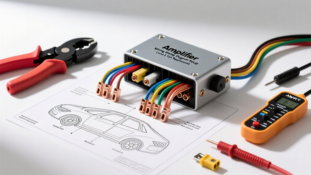
Executing the Amplifier Wiring Diagram: Beyond the Theory
A theoretical amplifier wiring diagram provides the logical path for current flow, signal routing, and remote triggering. However, the gap between a schematic and a reliable, high-fidelity installation is defined by tooling precision and material quality. When installing a high-current Class D monoblock or a multi-channel amplifier, relying on budget materials or improvised tools inevitably leads to voltage drop, thermal runaway, and catastrophic electrical failure. This analysis breaks down the exact costs, specialized tooling, and hidden material requirements necessary to execute a professional-grade amplifier wiring diagram safely and efficiently.
Essential Tool Inventory for High-Current Audio Installs
Executing a proper amplifier wiring diagram requires more than a basic socket set. High-current DC environments demand specialized termination tools to ensure milliohm-level resistance at every connection point.
Precision Hex Crimpers vs. Indent Crimpers
For 4 AWG and 1/0 AWG Oxygen-Free Copper (OFC) power wire, standard indent crimpers or hammer-style lug crimpers are unacceptable. Indent crimpers leave air pockets within the copper strands, leading to oxidation and increased DC resistance over time. Professionals must use a 4-ton or 6-ton ratcheting hex crimper (such as those from IWISS or Knoweasy) with precision-machined dies. For 4 AWG wire (approximately 25mm² cross-section), a 10mm hex die compresses the 1,011 copper strands into a solid, gas-tight block. This ensures the terminal can handle the 120A+ transient current spikes of a 1000W RMS amplifier without thermal degradation.
Digital Multimeters (DMM) and Voltage Drop Testing
A true-RMS Digital Multimeter (like the Fluke 87V) is mandatory for verifying the amplifier wiring diagram post-installation. You must measure the voltage drop across the ground connection. According to SAE standards, a properly terminated ground to bare chassis metal should exhibit a voltage drop of less than 0.1V under full load. If your DMM reads 0.3V or higher across the ground wire, your amplifier will experience clipping, dynamic compression, and potential alternator whine. Additionally, a DMM is required to verify the remote turn-on wire (typically Pin 7 on an ISO 10487 harness or the aftermarket blue/white wire) is delivering a clean 12V+ signal without AC ripple.
Material Cost Breakdown: 4-Gauge vs. 1/0-Gauge OFC
The most critical decision when planning your amplifier wiring diagram budget is selecting the correct American Wire Gauge (AWG) and conductor material. Copper-Clad Aluminum (CCA) wire is cheaper but possesses 30% higher resistance than OFC, requiring you to upsize the gauge to compensate. Below is a cost and specification analysis for a standard 18-foot run (battery to trunk).
| Material Type | AWG Size | Strand Count | Max Amperage (SAE J1128) | Est. Kit Cost (OEM Quality) | Recommended Amp RMS |
|---|---|---|---|---|---|
| CCA (Budget) | 4 AWG | ~400 | 85A | $45 - $65 | Up to 400W |
| OFC (Professional) | 4 AWG | 1,011 | 120A | $110 - $150 | Up to 800W |
| OFC (High-Power) | 1/0 AWG | 4,118 | 250A | $220 - $300 | 1000W - 2500W |
While a CCA kit saves roughly $80 upfront, the long-term cost includes accelerated oxidation at the crimp joints. OFC wire, compliant with SAE J1128 Low Tension Primary Cable standards, guarantees long-term conductivity and flexibility, making it the only viable choice for serious audio builds.
Hidden Costs in Amplifier Wiring Diagrams
Novice installers often budget for the main power wire, ground wire, and fuse, but overlook the ancillary components required to complete the amplifier wiring diagram correctly. These hidden costs can add $75 to $150 to your final bill.
Distribution Blocks and ANL Fuses
When running power to multiple amplifiers, a distribution block is required. Avoid blocks with Phillips-head set screws, which strip easily under high torque. Invest $30-$50 in solid brass distribution blocks with hex-key set screws. Furthermore, the main power fuse must be an ANL style, placed within 18 inches of the battery positive terminal. A high-quality ANL fuse holder with gold-plated brass contacts costs around $25, whereas cheap zinc-alloy holders introduce unnecessary resistance and can melt under sustained 80A+ loads.
RCA Shielding and Remote Turn-On Relays
Signal integrity is just as vital as power delivery. Twisted-pair, shielded RCA cables ($40-$80) are required to reject Electromagnetic Interference (EMI) from the vehicle's CAN bus and alternator. Additionally, if your amplifier wiring diagram includes multiple amplifiers or a DSP, the head unit's remote turn-on lead (max 300mA) will be overloaded. You must purchase a standard 30A Bosch-style 5-pin relay ($5-$10) to isolate the head unit from the high-current remote triggers of the amplifiers.
Real-World Failure Modes from Improper Tooling
Deviating from professional tooling and material standards results in specific, predictable failure modes in car audio systems:
- Cold Joints and Thermal Runaway: Using pliers to crush a 4 AWG ring terminal instead of a hex crimper creates a high-resistance 'cold joint'. Under heavy bass transients, this joint heats up, melting the ANL fuse holder and potentially causing an engine bay fire.
- Galvanic Corrosion at Ground Points: Failing to sand the chassis ground down to bare steel, or failing to coat the terminal with dielectric grease (e.g., Permatex 22058), allows moisture to cause galvanic corrosion. This increases ground impedance, causing the amplifier to enter 'protect mode' during high-volume playback.
- Alternator Whine via Ground Loops: If the RCA cables are routed on the same side of the vehicle as the power wire (violating basic amplifier wiring diagram routing rules), or if the RCA shields are compromised, the alternator's AC ripple will be amplified, resulting in a high-pitched whine that scales with engine RPM.
- Remote Wire Voltage Drop: Splicing the remote turn-on wire using 'scotch locks' or T-taps instead of solder-seal butt connectors leads to micro-arcing and voltage drop. The amplifier will randomly shut off when hitting bumps or during high-vibration driving conditions.
Authoritative References
For further technical validation on automotive electrical standards and wiring methodologies, consult the following resources:
- SAE International: J1128 Low Tension Primary Cable Standards - Defines the thermal and physical requirements for automotive copper wiring.
- Crutchfield Car Audio Amplifier Installation Guide - Industry-standard practices for routing, fusing, and terminating aftermarket audio gear.
- Fluke Corporation: How to Measure Voltage Drop - Methodologies for using a DMM to diagnose high-resistance grounds and power feeds in DC circuits.