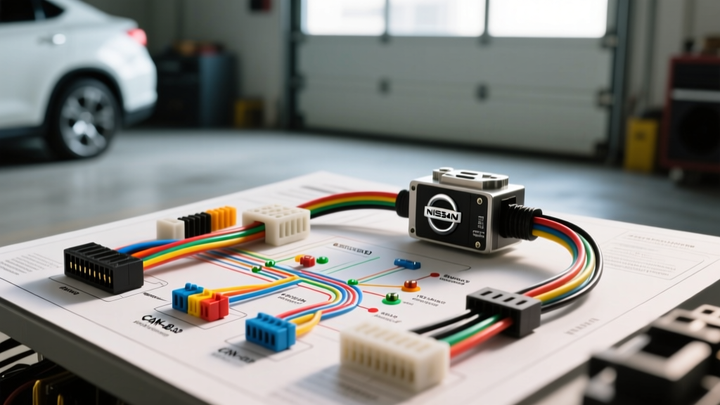
Introduction to Modern Nissan Audio Architecture
Upgrading the head unit in a modern Nissan vehicle requires far more than matching standard ISO or EIA/TIA wire colors. Starting around 2016, Nissan transitioned heavily toward proprietary 40-pin and 20-pin main harness connectors, integrating the infotainment system deeply into the vehicle's Controller Area Network (CAN-bus). For automotive electrical technicians and advanced DIYers, understanding the Nissan stereo wiring diagram is no longer just about finding the 12V constant and accessory wires; it is about navigating data packets, retaining Active Noise Cancellation (ANC), and avoiding catastrophic damage to OEM CMOS cameras.
This advanced technical deep dive dissects the 40-pin main connector found in popular platforms like the Altima, Maxima, and Rogue. We will explore CAN-bus integration, the notorious 6-volt backup camera trap, and the specific protocols required to bypass Bose amplified systems without losing chime retention. For comprehensive factory electrical schematics, technicians frequently cross-reference the NICOclub Factory Service Manual repository, which remains the gold standard for Nissan-specific wiring verification.
Decoding the Nissan 40-Pin Main Harness Pinout
The primary 40-pin connector handles power, ground, illumination, and high-speed CAN-bus communication. Unlike older vehicles where the head unit directly drove the speakers, modern Nissan base and premium systems use this 40-pin harness primarily for data and power, while a secondary 20-pin or 32-pin harness handles the analog or differential audio signals. Below is the critical pinout for the 40-pin power and data connector.
| Pin | Wire Color | Function | Technical Notes |
|---|---|---|---|
| 1 | Green | CAN-H (High) | Requires 120-ohm termination if testing bus resistance. |
| 2 | Blue | CAN-L (Low) | Operates at 1.5V - 3.5V differential. |
| 15 | Yellow/Red | 12V Constant (B+) | Fused at 15A in the IPDM (Intelligent Power Distribution Module). |
| 16 | Green/White | 12V Accessory (ACC) | Triggered via BCM (Body Control Module) logic. |
| 24 | Black | Chassis Ground | Must be terminated to bare metal; do not daisy-chain. |
| 33 | Red/Blue | Illumination | PWM dimming signal; do not use as a standard 12V trigger. |
| 38 | White/Green | Reverse Trigger | Logic level output for backup camera activation. |
When integrating an aftermarket radio, you must use a CAN-bus translation module (such as the Axxess XSVI-4803-NAV or Metra 40-NI06). These modules intercept the CAN-H and CAN-L signals on Pins 1 and 2, translating the BCM's digital 'ignition on' commands into a standard 12V accessory output for the aftermarket head unit's red wire. According to SAE J1939 standards governing heavy and light-duty CAN networks, improper termination or splicing into the CAN bus can introduce signal reflection, causing widespread BCM faults.
The 6-Volt Backup Camera Trap
One of the most costly mistakes made during Nissan stereo installations is frying the OEM backup camera. Unlike universal aftermarket cameras that require a 12V power supply, Nissan's OEM CMOS backup cameras are powered by a dedicated 6-volt regulator located inside the factory head unit or the AV control unit.
Retention Protocol
- The Problem: If you wire the OEM camera's power wire to the aftermarket head unit's 12V reverse trigger, you will instantly overvoltage and destroy the camera's internal IC.
- The Solution: You must use a specialized camera retention harness (e.g., Metra 40-NI06-CAM) that steps the 12V reverse trigger down to 6V, or utilize an interface module that commands the BCM to supply the OEM 6V power via the camera's dedicated shielded twisted pair.
- Signal Conversion: Nissan cameras output an NTSC composite signal, but it is often carried over a shielded twisted pair (STP) rather than a standard RCA. A differential-to-single-ended converter is required to adapt this to the aftermarket radio's RCA video input.
Bose Amplified Systems and Active Noise Cancellation (ANC)
Nissan vehicles equipped with the Bose premium audio package present a unique set of challenges. The Bose amplifier does not accept standard high-level speaker wire inputs. Instead, it relies on low-level differential analog signals or, in newer models, a proprietary digital audio bus.
Active Noise Cancellation (ANC) and Chime Retention
In models like the Altima and Maxima, the factory radio acts as the DSP (Digital Signal Processor) for the Active Noise Cancellation system. Microphones located in the headliner feed ambient cabin noise data to the OEM radio, which then generates an out-of-phase frequency sent to the Bose subwoofer to cancel engine drone.
If you remove the OEM radio without an ANC retention module, you will lose the cancellation effect, resulting in a noticeable increase in low-frequency cabin boom. Furthermore, Nissan routes critical vehicle warning chimes (seatbelt, turn signals, door ajar) through the audio system. Advanced integration harnesses capture these chime audio signals from the BCM and mix them into the aftermarket radio's auxiliary or dedicated chime input channels to ensure safety compliance.
Steering Wheel Controls: Resistor Ladder vs. CAN-Bus
Understanding the evolution of Nissan's Steering Wheel Controls (SWC) is vital for proper interface programming.
- Pre-2015 (Analog Resistor Ladder)
- Older Nissan models used a simple analog voltage divider network. Pressing a button changed the resistance on the SWC wire. Interfaces like the Axxess ASWC-1 read these voltage drops to map button functions.
- 2016-Present (CAN-Bus SWC)
- Modern Nissans transmit SWC inputs as CAN-bus data frames (typically on the 0x1A4 or 0x2C1 message IDs). The steering wheel control module sends a digital packet to the BCM, which then relays it to the head unit. Aftermarket interfaces must be flashed with the specific Nissan CAN firmware to decode these packets and translate them into standard IR or hardwired SWC signals for Pioneer, Kenwood, or Alpine receivers.
Wire Gauge Specifications and Routing Best Practices
When running new wiring for aftermarket amplifiers or bypassing the Bose system, adhering to proper AWG (American Wire Gauge) standards is critical to prevent voltage drop and thermal events. The Crutchfield Vehicle Database consistently highlights the importance of using Oxygen-Free Copper (OFC) rather than Copper-Clad Aluminum (CCA) for Nissan's tight firewall grommet routing.
| Application | Recommended AWG (OFC) | Max Current / Distance | Nissan-Specific Routing Notes |
|---|---|---|---|
| Main Amp Power | 4 AWG or 2 AWG | Up to 150A / 15 ft | Route through the main firewall grommet behind the glovebox; avoid the hood release cable. |
| Subwoofer Runs | 12 AWG or 10 AWG | Up to 40A / 20 ft | Run down the passenger side B-pillar to avoid interference with driver-side airbag modules. |
| Standard Speakers | 18 AWG | N/A | Use T-S connectors at the door boot to maintain factory moisture seals. |
| Bose Low-Level | 20 AWG Shielded | Signal only | Must be shielded twisted pair (STP) to prevent alternator whine from the high-current CVT alternator. |
Troubleshooting Common Nissan Aftermarket Stereo Faults
Even with the correct Nissan stereo wiring diagram, integration modules can exhibit specific failure modes. Use this decision tree to diagnose common post-installation issues.
- Symptom: Radio turns on, but no audio is heard from any speaker.
Cause: The factory Bose amplifier is not turning on.
Fix: Verify that the interface module is sending a 12V remote turn-on signal to the Bose amp's trigger wire (usually Pin 12 on the Bose sub-harness). Ensure the interface dip-switches are set to 'Bose' mode. - Symptom: Backup camera displays a blue screen or 'No Signal' when in reverse.
Cause: The 6V camera power is missing, or the composite video signal is ungrounded.
Fix: Test the camera power wire at the trunk lid hinge with a multimeter; it must read exactly 5.8V to 6.2V. If 12V is present, replace the step-down resistor immediately. Check the RCA ground shield for continuity. - Symptom: Intermittent CAN-bus errors on the dash (e.g., 'Key Not Detected' or battery drain).
Cause: The CAN-bus interface module is failing to go to sleep when the vehicle is locked.
Fix: Update the interface module's firmware via USB. Ensure the CAN-H and CAN-L wires are spliced using military-grade T-taps or solder-and-heat-shrink, as high-resistance splices cause the BCM to stay awake polling the network. - Symptom: Severe alternator whine that pitches up and down with engine RPM.
Cause: Ground loop introduced by using the factory Bose amplifier ground.
Fix: The Bose amp ground in Nissans is often tied to a shared audio ground point that carries noise from the fuel pump module. Run a dedicated 10 AWG ground wire from the aftermarket DSP/Amp directly to a clean, sanded chassis bolt in the trunk or under the seat.
Conclusion
Successfully navigating a Nissan stereo wiring diagram requires a paradigm shift from simple wire-matching to network integration. By respecting the 6V camera architecture, properly terminating CAN-bus lines, and utilizing the correct shielded wire for low-level audio signals, you can achieve a flawless, OEM-plus aftermarket installation. Always verify pinouts with a digital multimeter and consult factory service data before cutting a single wire.