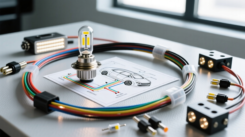
The Critical Role of Lamp Wiring Diagrams in Audio Upgrades
When executing a comprehensive car audio and stereo modification, the focus often narrows to amplifier power wire routing, RCA signal integrity, and speaker phase alignment. However, a truly professional, OEM-grade installation requires seamless integration with the vehicle's interior lighting network. This is where factory lamp wiring diagrams become an indispensable asset for the 12V installer. Whether you are wiring the illumination dimmer circuit for an aftermarket double-DIN head unit or integrating door-triggered footwell LEDs that sync with your audio system's power state, guessing wire functions will inevitably lead to blown Body Control Module (BCM) fuses, CAN-bus faults, or melted harnesses.
Modern vehicles no longer use simple analog rheostats for dashboard dimming. Instead, they rely on Pulse Width Modulation (PWM), LIN-bus, or CAN-bus signals to control interior and exterior lamp states. By cross-referencing accurate lamp wiring diagrams with the Electronic Industries Alliance (EIA) color codes, you can safely bridge the gap between legacy analog audio equipment and modern multiplexed automotive electrical systems.
Head Unit Illumination: Decoding the Dimmer Circuit
The most common intersection between car audio and lamp circuits is the head unit illumination wire. According to the EIA RS-770 standard, aftermarket stereo harnesses utilize specific color codes for lighting integration. The solid Orange wire provides a +12V signal indicating that the parking or headlights are on, while the Orange with White Stripe wire carries the variable voltage (or PWM signal) used to dim the display.
The PWM Dimming Challenge in Late-Model Vehicles
If you consult the lamp wiring diagrams for a 2016+ Chevrolet Silverado or a 2018+ Ford F-150, you will notice that the dash lamp circuit does not output a smooth 0V to 12V analog drop when the dimmer switch is rolled. Instead, the BCM outputs a fixed 12V square wave (PWM) and varies the duty cycle to change the perceived brightness of the dash LEDs. If you splice an aftermarket stereo's analog Orange/White dimmer wire directly into a PWM lamp circuit, the stereo's internal microcontroller will misinterpret the signal, resulting in a display that violently flickers or fails to dim entirely.
Expert Solution: To resolve this, you must use a PWM-to-Analog signal converter (such as the PAC TRUNK-LOC or an equivalent interface module). This device reads the high-frequency PWM signal from the OEM lamp circuit and outputs a clean, variable 0-12V analog signal to the stereo's Orange/White wire.
EIA vs. OEM Illumination Wire Reference
| Function | EIA Aftermarket Color | Common OEM Wire Colors (Varies by Make) | Wire Gauge / Spec |
|---|---|---|---|
| Illumination (+12V Trigger) | Orange | Red/Black, Green/Yellow, Brown/White | 18 AWG (SAE J1128) |
| Illumination Dimmer (Variable) | Orange/White | Gray/Red, Violet/White, LIN-bus Data | 18 AWG (SAE J1128) |
| Accessory (+12V Switched) | Red | Yellow/Blue, Pink, Green/Orange | 16 AWG (SAE J1128) |
Project: Integrating Door-Triggered Footwell LEDs with Your Stereo
A popular upgrade modification is installing custom footwell LED accent lighting that illuminates when the doors open (triggered by the dome/courtesy lamp circuit) but can also be overridden or synced with the stereo's accessory state. Tapping directly into the dome lamp wiring without consulting the lamp wiring diagrams and understanding the BCM's current-sensing topology is a recipe for disaster.
The Danger of Direct Splicing and Backfeed
On modern multiplexed networks, the BCM monitors the voltage drop across the dome lamp circuit to detect blown bulbs or short circuits. Splicing an LED strip directly into the dome lamp trigger wire introduces a parasitic draw and alters the circuit's resistance. This will cause the BCM to throw a U-code (e.g., U0140 Lost Communication with BCM) or shut down the circuit entirely to protect the solid-state relay inside the module.
Required Tools and Materials
- Bosch-style 12V SPDT Automotive Relay (30A minimum)
- 1N4001 Rectifier Diodes (for signal isolation)
- Add-A-Circuit Fuse Tap (matched to OEM fuse profile: ATO, Mini, or Micro2)
- 18 AWG Primary Wire (Signal/Trigger)
- 14 AWG Primary Wire (LED Power Feed)
- M6 Ring Terminals and Heat Shrink (Adhesive-lined)
- Digital Multimeter (DMM) with duty-cycle and frequency testing
Step-by-Step Relay Isolation Wiring Procedure
- Identify the Trigger Source: Consult the vehicle-specific lamp wiring diagrams to locate the BCM output pin for the dome/courtesy lamp. Verify with a DMM that the wire drops to ground (0V) when the door opens and rises to 12V when the door closes (or vice versa, depending on whether it's a switched-ground or switched-power circuit).
- Establish Isolated Power: Use an Add-A-Circuit tap on a constant 12V fuse in the interior fuse box. Run 14 AWG wire from the tap to Pin 30 (Normally Open / Common) of your SPDT relay. Install an inline 5A blade fuse within 6 inches of the tap.
- Wire the Trigger Coil: Connect the OEM dome lamp trigger wire to Pin 86 of the relay. Critical Step: Solder a 1N4001 diode in parallel across Pins 85 and 86, with the cathode (silver stripe) facing Pin 86. This flyback diode absorbs the inductive voltage spike generated when the relay coil de-energizes, protecting the BCM's delicate driver transistor.
- Ground the Relay: Connect Pin 85 to a verified, unpainted chassis ground using an M6 ring terminal. Torque the grounding bolt to 10 Nm (7.4 lb-ft) to ensure zero voltage drop.
- Connect the Load: Wire the positive lead of your footwell LED strip to Pin 87. Ground the LED strip's negative lead to the chassis. When the door opens, the BCM triggers the relay coil, closing the contact between Pin 30 and Pin 87, illuminating the LEDs using isolated battery power without backfeeding the BCM.
Advanced Troubleshooting: CAN-Bus and Voltage Drop
Even with meticulous adherence to lamp wiring diagrams, integration issues can arise due to degraded chassis grounds or aftermarket CAN-bus decoders. Below is a diagnostic matrix for common failures encountered during stereo and lighting integration projects.
Symptom-Cause-Fix Matrix
| Symptom | Root Cause | Expert Fix |
|---|---|---|
| Stereo display flickers rapidly when headlights are turned on. | Aftermarket dimmer wire connected directly to an OEM PWM lamp circuit. | Install a PWM-to-Analog signal converter module between the OEM lamp wire and the stereo's Orange/White wire. |
| Footwell LEDs stay on after doors close and vehicle goes to sleep. | BCM uses a switched-ground (low-side driver) dome circuit, but relay is wired for switched-power. | Reconfigure relay wiring. Use Pin 85 for the BCM switched-ground trigger and supply +12V to Pin 86 from a constant source. |
| Radio presets and clock reset every time the vehicle is restarted. | Constant 12V (Yellow) and Switched 12V (Red) wires swapped at the head unit harness, or excessive voltage drop on the Add-A-Circuit tap. | Verify pinout with DMM. Ensure Add-A-Circuit tap is on a true constant fuse (e.g., Horn, Hazard) and check for loose crimps causing >0.2V drop. |
| Interior lamp circuit throws 'Bulb Out' warning on dash after LED mod. | LED strip draws significantly less current than the OEM incandescent dome bulb, triggering the BCM's open-circuit protection. | Install a 10-ohm, 10W ceramic power resistor in parallel with the LED load to simulate the current draw of the factory bulb. |
Authoritative References and Standards
To ensure long-term reliability and safety in your automotive electrical modifications, always adhere to established engineering standards. The wire gauge specifications and insulation requirements referenced in this guide are derived from the SAE J1128 Low Tension Primary Cable Standard. For comprehensive guidelines on aftermarket electronic integration and avoiding CAN-bus interference, consult the technical whitepapers available through the SEMA Garage. Finally, relay pinout configurations and flyback diode requirements are based on standard automotive electrical architecture documented by Bosch Mobility Solutions.