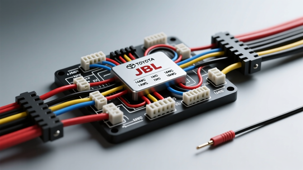
The Challenge of Toyota's JBL Differential Audio Architecture
Upgrading the audio system in a Toyota equipped with the factory JBL premium package is notoriously complex. Unlike standard aftermarket or base-model systems that use single-ended, ground-referenced speaker outputs, the Toyota JBL head unit outputs a differential (balanced) low-level signal directly to the factory JBL amplifier. This architecture is designed to reject electromagnetic interference (EMI) over long wire runs, but it creates a massive hurdle for car audio modifiers.
If you attempt to tap into the factory speaker wires using a standard aftermarket amplifier's high-level inputs—which typically share a common chassis ground—you will short-circuit the head unit's internal pre-amplifier IC, permanently destroying the radio. To execute a proper upgrade or modification project, you must utilize a specialized bypass interface and thoroughly understand the Toyota JBL amplifier wiring diagram to safely isolate the data, trigger, and audio signals.
Factory JBL Amplifier Pinout Reference
The factory JBL amplifier (commonly located under the passenger seat in Tacomas and Tundras, or behind the dash kick-panel in Camrys and 4Runners) relies on two primary connectors: a 10-pin power/data harness and a 16-pin balanced audio harness. Below is the definitive pinout reference for the 2005-2015 generation Toyota JBL systems.
| Connector / Pin | Function | Wire Color | Specification / Notes |
|---|---|---|---|
| 10-Pin: Pin 1 | +12V Constant Battery | White w/ Red Stripe | Supplies memory and standby current. Factory wire is typically 10 AWG. |
| 10-Pin: Pin 2 | +12V Accessory (IGN) | Gray | Switched 12V+ from ignition cylinder. |
| 10-Pin: Pin 3 | Chassis Ground | White w/ Black Stripe | Must be secured to bare metal. Do not rely on seat bolts for aftermarket grounds. |
| 10-Pin: Pin 4 | AMP Turn-On / Data | Pink or Light Green | Carries the wake-up signal. On CAN-bus models, this is a multiplexed data line. |
| 16-Pin: Pins 1 & 2 | Front Left (+ / -) | Pink / Purple | Balanced differential output. Do NOT ground the (-) wire. |
| 16-Pin: Pins 3 & 4 | Front Right (+ / -) | Light Green / Blue | Balanced differential output. |
| 16-Pin: Pins 5 & 6 | Rear Left (+ / -) | Black / Yellow | Balanced differential output. |
| 16-Pin: Pins 7 & 8 | Rear Right (+ / -) | Red / White | Balanced differential output. |
Note: Pinouts can vary slightly by exact model year and platform (e.g., E35 vs E39 head unit codes). Always verify with a digital multimeter (DMM) before splicing.
The Bypass Modification: Interface Integration
To retain the factory steering wheel controls, backup camera, and differential audio integrity while adding an aftermarket amplifier, the industry standard is to use an integration module like the Metra Electronics TYTO-01 Interface. This device safely sums the differential signals into single-ended RCA outputs and handles the CAN-bus or discrete AMP turn-on requirements.
Step-by-Step Wiring Integration
- Disconnect the Battery: Remove the negative terminal and isolate it. Wait 10 minutes for the SRS (airbag) system capacitors to discharge before working under the passenger seat.
- Unplug Factory Harnesses: Depress the locking tabs on the 10-pin and 16-pin JBL connectors and remove the factory amplifier.
- Splice the Interface Harness: Using the provided TYTO-01 T-harness, connect it inline between the vehicle's factory JBL plugs and the interface module. If hardwiring, use 18 AWG stranded copper wire, solder all connections, and seal with dual-wall adhesive heat shrink. Never use T-taps or Scotchlocks on Toyota data or balanced audio lines.
- Route RCA Cables: Run high-quality, shielded RCA cables from the interface module to your new aftermarket amplifier. Keep RCA cables on the opposite side of the vehicle from the new power wire to prevent inductive coupling (alternator whine).
- Verify Turn-On Signal: Use a DMM to verify that the interface's remote turn-on lead outputs +12V when the ignition is in the 'ACC' or 'ON' position.
Upgrading Power Delivery: AWG and Routing Specs
The factory JBL amplifier power wire is typically 10 AWG or 12 AWG, which is sufficient for the ~35W x 4 channels the factory amp produces. However, if your modification project includes an aftermarket 5-channel amplifier (e.g., 100W x 4 + 600W x 1), the factory wiring will cause severe voltage sag and trigger the amp's protection mode.
Power Wire Routing and Torque Specs
According to the SAE J1128 Low Tension Primary Cable Standard, automotive wiring must handle specific thermal and current loads. For a modern Class-D amplifier drawing up to 60 amps, you must run new 4 AWG Oxygen-Free Copper (OFC) wire directly from the battery.
- Fusing: Install an ANL fuse holder within 18 inches of the battery positive terminal. Size the fuse to 80A (assuming a 60A max draw, providing a 25% safety buffer per SAE guidelines).
- Firewall Pass-Through: Route the 4 AWG wire through the main factory rubber grommet on the driver's side firewall. Use a plastic trim tool to create a slit, and apply dielectric grease to seal the rubber after the wire passes through to prevent moisture ingress.
- Termination Torque: When connecting the ring terminal to the battery, torque the M8 nut to 5-7 Nm. Over-tightening can strip the soft lead of the battery post.
- Chassis Ground: Find a factory M8 or M10 bolt in the rear cargo area or under the passenger seat. Remove the bolt, use a wire brush to scrape away all paint and primer down to bare steel, and reattach the 4 AWG ground ring terminal using a star washer. Torque to 12-15 Nm and coat the area with clear nail polish or corrosion inhibitor to prevent rust.
Troubleshooting Decision Tree: Common JBL Integration Issues
When modifying Toyota JBL systems, installers frequently encounter specific electrical anomalies. Use this diagnostic tree to resolve them:
- Symptom: Severe Alternator Whine that pitches up with engine RPM.
- Cause: Ground loop or inductive coupling.
- Fix: Verify the aftermarket amp ground and the interface module ground share the same bare-metal chassis point. Ensure RCA cables are not zip-tied to the 4 AWG power wire.
- Symptom: Head Unit Pops Loudly Upon Engine Shutoff.
- Cause: Improper remote turn-on sequencing or CAN-bus delay failure.
- Fix: Adjust the DIP switches on the TYTO-01 interface to enable the 'Amp Turn-On Delay' setting, allowing the head unit to fully boot before sending the +12V trigger to the aftermarket amp.
- Symptom: Parasitic Battery Drain (Dead battery after 2 days).
- Cause: The interface module is keeping the CAN-bus awake, or the amp remote wire is back-feeding voltage into the factory ACC circuit.
- Fix: Use a DMM to check for amperage draw at the battery with the vehicle asleep (doors locked, key fob 10 feet away). If draw exceeds 50mA, install a relay on the remote turn-on line to isolate the aftermarket amp's trigger circuit from the Toyota data bus. Refer to the Crutchfield Amplifier Installation Guide for relay wiring diagrams.
Final Verification and System Tuning
Before reinstalling the passenger seat or trim panels, perform a baseline voltage test. With the vehicle running and the aftermarket amplifier playing a 50Hz sine wave at 75% volume, measure the DC voltage at the amplifier's power and ground terminals. If the voltage drops below 12.2V, your 4 AWG power run is insufficient, or your ground point has excessive resistance. A properly executed Toyota JBL bypass will yield a clean noise floor, retain all factory steering wheel audio controls, and provide the robust, unclipped RCA signal required to drive high-fidelity aftermarket speakers and subwoofers.