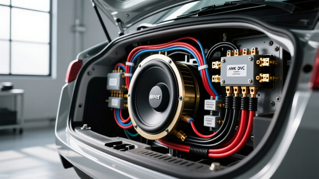
The Electromagnetic Reality of Subwoofer Impedance
Transitioning from plug-and-play audio kits to custom high-current subwoofer arrays requires a fundamental understanding of electromagnetism and DC circuit physics. This advanced car subwoofer wiring guide bypasses entry-level assumptions to focus on impedance loading, voltage drop mitigation, and signal integrity. When wiring subwoofers, you are not merely connecting positive and negative terminals; you are manipulating the electrical load presented to the amplifier's output stage. Mismanaging this load can result in catastrophic MOSFET failure, thermal compression, or severe clipping.
Dual Voice Coil (DVC) Configurations and Amplifier Stability
Dual Voice Coil (DVC) subwoofers offer wiring flexibility, allowing you to tailor the final impedance to match your amplifier's optimal efficiency curve. However, wiring a DVC 2-ohm subwoofer in parallel to achieve a 1-ohm load is often a mistake. While many modern Class D amplifiers advertise 1-ohm stability, operating at this threshold drastically reduces the damping factor, limits the amplifier's ability to control back-EMF (electromotive force), and pushes the output transistors to their thermal limits. According to the CTA-2015 Mobile Audio Power Standard, RMS ratings must be verified at specific impedance thresholds, and an amplifier rated for 1000W at 2 ohms may only safely produce 600W at 1 ohm before triggering thermal protection.
DVC Impedance Matrix Reference
| Subwoofer Type | Wiring Configuration | Final Impedance (Ohms) | Amplifier Load Status |
|---|---|---|---|
| DVC 2-Ohm | Series | 4 Ohms | Highly Stable / Low Current |
| DVC 2-Ohm | Parallel | 1 Ohm | Extreme Stress / High Heat |
| DVC 4-Ohm | Series | 8 Ohms | Ultra Stable / Minimal Power |
| DVC 4-Ohm | Parallel | 2 Ohms | Optimal Class D Efficiency |
| DVC 2-Ohm (x2) | Series-Parallel | 2 Ohms | Optimal Class D Efficiency |
AWG Sizing, OFC vs. CCA, and Voltage Drop Dynamics
The most critical failure point in high-output car audio systems is undersized power wire. Many commercial wiring kits utilize Copper-Clad Aluminum (CCA) instead of Oxygen-Free Copper (OFC). CCA wire has approximately 40% less conductivity than pure copper, meaning a 4 AWG CCA wire performs electrically similar to an 8 AWG OFC wire. When calculating wire gauge, you must account for the total length of the circuit (positive and negative paths) and the specific DC resistance of the conductor.
Calculating True Voltage Drop
Voltage drop is calculated using the formula: VD = I × R × 2 × L, where I is current in amps, R is the resistance per foot of the specific AWG, and L is the one-way length in feet. If your amplifier draws 80A and experiences a 2V drop, it is effectively operating at 12.4V instead of 14.4V, resulting in a 15% loss in potential RMS power output. Furthermore, the concept of 'skin effect'—where high frequencies travel on the outside of the conductor—is largely irrelevant in subwoofer wiring. Sub-bass frequencies (20Hz to 80Hz) utilize the entire cross-sectional area of the wire, making strand count and overall copper mass the only variables that matter.
OFC AWG Capacity Reference Chart (14.4V System)
| AWG Size | Max Continuous Current | Max RMS Power (Class D) | Max Length (for <0.5V Drop) |
|---|---|---|---|
| 8 AWG OFC | 50 Amps | 400 Watts | 12 Feet |
| 4 AWG OFC | 90 Amps | 800 Watts | 14 Feet |
| 2 AWG OFC | 125 Amps | 1200 Watts | 16 Feet |
| 1/0 AWG OFC | 175 Amps | 2000+ Watts | 18 Feet |
Always adhere to SAE J1128 standards for automotive low-tension primary cable to ensure the wire jacket can withstand under-hood temperatures and resist abrasion against the vehicle chassis.
Chassis Grounding Physics and the Dielectric Barrier
A vehicle's chassis is not a perfect conductor; it is constructed of stamped steel joined by spot welds, seam sealer, and paint. These materials act as dielectrics (insulators). A common amateur mistake is bolting a ground ring terminal over factory paint or undercoat, creating a high-resistance connection that leads to alternator whine and amplifier clipping.
Proper Grounding Procedure:
- Locate a structural, double-walled section of the chassis within 18 inches of the amplifier.
- Use 80-grit sandpaper or a rotary wire brush to remove all paint, primer, and rust down to bare, shiny metal.
- Use a copper or brass grounding block, or a heavy-duty tinned copper ring terminal (never use spade terminals for high-current grounds).
- Secure the ground using an M8 or M10 grade 8.8 steel bolt, torqued to 15-20 Nm to ensure maximum surface area contact and prevent vibration loosening.
- Critical: Do NOT apply dielectric grease between the terminal and the chassis. Grease is an insulator and will increase resistance. Apply dielectric grease or clear nail polish over the tightened connection to seal out moisture and prevent galvanic corrosion.
Remote Turn-On Current Limits and Relay Integration
The remote turn-on output (typically a blue/white wire) on an aftermarket head unit is not designed to carry heavy loads. Most head unit PCB traces for the remote output are fused internally at 300mA to 500mA. A single Class D mono-block amplifier draws roughly 20mA to 50mA from the remote wire. However, if you are powering an amplifier, a standalone DSP, and a line driver simultaneously, you can easily exceed the head unit's current limit, burning the internal trace and killing the remote output.
To prevent this, utilize a standard Bosch-style 30A SPDT (Single Pole Double Throw) relay wired as follows:
- Pin 30: 12V+ constant from the battery (via a 5A inline ATC fuse).
- Pin 87: Output to the amplifier(s) and DSP remote terminals.
- Pin 86: 12V+ trigger from the head unit's remote turn-on wire.
- Pin 85: Solid chassis ground.
This setup ensures the head unit only supplies the minimal current required to energize the relay's electromagnetic coil (~80mA), while the heavy lifting is handled by the direct battery feed.
Signal Routing, Mutual Inductance, and Ground Loops
Alternator whine is rarely caused by the RCA cables themselves; it is almost always a ground loop issue. A ground loop occurs when there is a difference in electrical potential between the ground reference of the head unit and the ground reference of the amplifier. Because the vehicle's chassis has inherent resistance, the 50A+ current drawn by the subwoofer amplifier creates a voltage drop across the chassis. If the RCA shields are tied to this fluctuating ground potential, the amplifier interprets the voltage differential as an audio signal, resulting in a high-pitched whine that scales with engine RPM.
To mitigate this, route your RCA signal cables strictly on the opposite side of the vehicle from the 12V+ power wire. If crossing the power wire is unavoidable, do so at a strict 90-degree angle to minimize mutual inductance and electromagnetic interference (EMI). For advanced setups, utilize twisted-pair RCA cables with high-density braided shields, and ensure all audio equipment shares a common, centralized ground point (star grounding) rather than relying on distributed chassis grounds.
Authoritative References and Standards
For further technical validation on automotive electrical modifications and audio power ratings, consult the Mobile Electronics Association (MEA) installation guidelines and the Consumer Technology Association's CTA-2015 mobile audio power standards. Proper adherence to these protocols ensures system longevity, safety, and acoustic fidelity.