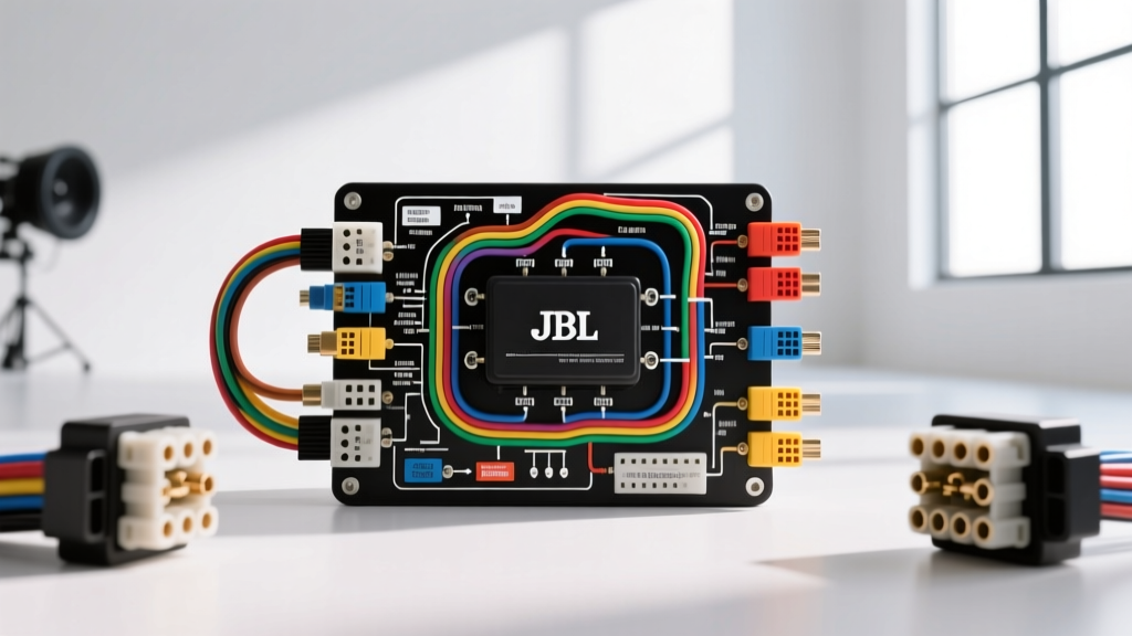
The Challenge of Toyota’s JBL Synthesis Architecture
Upgrading the audio system in late-model Toyota trucks and SUVs (specifically the 2016-2023 Tacoma, Tundra, and 4Runner) equipped with the JBL Synthesis audio system is notoriously complex. Unlike standard automotive audio setups where the head unit outputs pre-amplified RCA signals or standard high-level speaker wires, the Toyota JBL system utilizes a proprietary multi-channel Class-D amplifier, CAN-bus data integration, and Active Noise Cancellation (ANC). To successfully integrate aftermarket amplifiers, DSPs, or subwoofers, you must thoroughly understand the factory amp wiring Toyota JBL wiring diagram to avoid triggering CAN-bus sleep modes, losing vehicle chimes, or destroying aftermarket gear with multiplexed signals.
This practical how-to guide breaks down the exact pinouts, wire gauges, and integration strategies required to bypass or tap into the OEM JBL amplifier safely, referencing established integration standards from Crutchfield's Toyota JBL Integration Guide and OEM service manuals.
Understanding the JBL Amplifier Connectors
The OEM JBL amplifier is typically located under the front passenger seat or behind the rear passenger-side quarter panel trim. It interfaces with the vehicle's electrical system via two primary connectors:
- E5 Connector (28-Pin): Handles primary 12V power, ground, and high-level speaker outputs to the cabin.
- E6 Connector (10-Pin): Handles CAN-bus data lines (CAN-H, CAN-L), ANC microphone inputs, and digital audio routing.
Critical Warning: Never attempt to tap directly into the E6 data pins for audio signals. These are low-voltage digital communication lines. Tapping them with an aftermarket Line Output Converter (LOC) will result in immediate data bus faults and potential ECU bricking.
Factory Amp Wiring Toyota JBL Wiring Diagram: 28-Pin E5 Pinout
Below is the reference pinout for the 28-pin E5 connector. Wire colors may vary slightly by exact model year, so always verify with a digital multimeter (DMM) before cutting or splicing.
| Pin Number | Function | Typical Wire Color | Wire Gauge (AWG) |
|---|---|---|---|
| 1 | +B (12V Constant Battery Power) | White | 10 AWG |
| 2 | GND (Chassis Ground) | White w/ Black Stripe | 10 AWG |
| 11 | Front Left Speaker (+) | Pink | 18 AWG |
| 12 | Front Left Speaker (-) | Purple | 18 AWG |
| 13 | Front Right Speaker (+) | Light Green | 18 AWG |
| 14 | Front Right Speaker (-) | Blue | 18 AWG |
| 27 | ACC / Ignition Sense | Gray | 20 AWG |
Note on Remote Turn-On: The JBL amplifier does not use a traditional 12V+ remote turn-on wire. It wakes up via the CAN-bus network. To trigger an aftermarket amplifier, you must either use a data interface module (like an iDatalink Maestro) or tap the Gray ACC wire (Pin 27) to drive a 12V relay that sends a dedicated remote signal to your aftermarket amp.
Step-by-Step Integration and Bypass Guide
To integrate an aftermarket DSP or amplifier, you must extract a clean, pre-processed audio signal. Because the JBL amp applies heavy factory EQ and crossover filters, tapping the speaker outputs post-amplifier requires signal summing and flattening.
Step 1: Access and Disconnect
- Disconnect the negative terminal of the vehicle's 12V battery and wait 5 minutes to allow the CAN-bus modules to enter sleep mode.
- Remove the passenger seat (four 14mm bolts) or rear quarter trim panel to expose the JBL amplifier.
- Unplug both the 28-pin and 10-pin connectors from the OEM amp.
Step 2: Tapping the Signal with a Summing LOC
According to the PAC Audio TOY-LOC Installation Manual, you must use a specialized integration harness that plugs inline between the OEM wiring and the JBL amp. This allows you to retain the factory amp for door speakers while extracting the signal for an aftermarket subwoofer or DSP.
- Connect the T-harness inline with the 28-pin E5 connector.
- Route the RCA outputs from the T-harness to your aftermarket Line Output Converter (LOC) or DSP.
- If you are completely bypassing the factory amp to run a full active DSP setup, you will need to hardwire the 18 AWG speaker outputs from the head unit's rear harness directly to your DSP's high-level inputs, completely removing the JBL amp from the circuit.
Step 3: Upgrading the Power Wire
The factory JBL amplifier is fed by a 10 AWG power wire. While sufficient for the OEM Class-D amp (which peaks around 400W total RMS), it is inadequate for aftermarket subwoofer amplifiers drawing 800W+.
- Up to 600W RMS: You can tap the factory 10 AWG +B wire using a high-quality distribution block, provided you upgrade the fuse at the battery from 30A to 40A.
- Over 600W RMS: Run a dedicated 4 AWG Oxygen-Free Copper (OFC) power wire directly from the battery to the trunk/rear cabin, utilizing an 80A ANL fuse within 12 inches of the battery terminal.
Critical Failure Modes: ANC, Chimes, and CAN-Bus Sleep
When working with the factory amp wiring Toyota JBL wiring diagram, installers frequently encounter three major failure modes. Understanding these will save you hours of troubleshooting.
1. Active Noise Cancellation (ANC) Feedback Loops
Toyota utilizes an ANC microphone mounted in the headliner that feeds inverted phase audio through the JBL amp to cancel engine drone. If you add an aftermarket subwoofer that plays low frequencies (under 100Hz), the ANC microphone will 'hear' the subwoofer, invert the signal, and send it back through the system. This creates a massive, booming feedback loop that can blow your subwoofers.
The Fix: You must physically disconnect the ANC microphone (located in the overhead console) or use a data-bypass harness that isolates the ANC pins on the 10-pin E6 connector. For more on automotive electromagnetic and acoustic interference, refer to SAE J1113 EMC Standards regarding in-cabin acoustic feedback.
2. Loss of Vehicle Chimes and Alerts
In modern Toyotas, the door-ajar chime, turn signal click, and hybrid/EV warning sounds are not generated by a physical buzzer. They are sent as digital data over the CAN-bus to the JBL amplifier, which then plays them through the front left door speaker. If you completely bypass or remove the JBL amp without a data retention module, you will lose all warning chimes, which is a safety and inspection hazard.
The Fix: Retain the OEM JBL amp to handle the front left door speaker and chimes, or install an iDatalink Maestro RR or PAC Audio data module that intercepts the CAN-bus chime data and routes it to an aftermarket speaker or standalone piezo buzzer.
3. The '10-Minute' CAN-Bus Sleep Cut-Off
If you use a simple 12V ACC tap to turn on your aftermarket DSP or amplifier, you may notice the audio system shutting off exactly 10 minutes after the vehicle is turned off, or failing to wake up properly. This is because the vehicle's Body Control Module (BCM) monitors current draw on the ACC circuit. If it detects an abnormal draw (like an aftermarket amp relay), it will forcefully cut the circuit to prevent battery drain.
The Fix: Always use a data-interface module to generate a clean, isolated 12V+ remote turn-on signal that mimics the OEM amp's wake-up sequence, ensuring the BCM does not flag a parasitic draw fault.
Final Verification and Testing
Before reassembling the interior trim, reconnect the 12V battery and perform a systematic verification:
- Turn the ignition to the 'ON' position (do not start the engine) and verify the aftermarket amp's remote terminal reads exactly 12V to 14.4V.
- Play a 0dB 50Hz sine wave track to verify the ANC has been successfully disabled (no low-frequency booming).
- Open the driver's door to confirm the door-ajar chime is still audible.
- Use a multimeter to verify that the OEM JBL amp ground wire shows less than 0.05 ohms of resistance to the bare chassis metal.
By strictly adhering to this factory amp wiring Toyota JBL wiring diagram and respecting the vehicle's CAN-bus architecture, you can achieve a seamless, high-fidelity aftermarket audio upgrade without sacrificing OEM safety features or vehicle functionality.