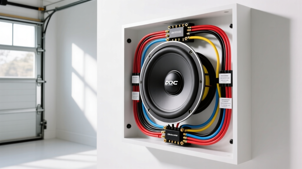
Introduction to DVC 4-Ohm Subwoofer Topologies
When wiring subwoofers in car audio environments, the electrical topology of Dual Voice Coil (DVC) 4-ohm drivers dictates amplifier stability, thermal headroom, and ultimate acoustic output. Unlike Single Voice Coil (SVC) configurations, a 12-inch DVC 4-ohm subwoofer presents two independent 4-ohm windings on a shared former. This allows the installer to manipulate the nominal impedance (Z) to match the amplifier's minimum stable load. It is critical to distinguish between nominal impedance (Z), which is an AC rating at a specific frequency (typically 1kHz, though subwoofers operate primarily below 80Hz), and DC resistance (Re). A multimeter reading across a single 4-ohm coil will typically display an Re of 3.2 to 3.6 ohms. Understanding this variance is the first step in preventing amplifier protection faults and ensuring accurate electrical modeling.
Voice Coil Impedance Matrix
The versatility of the DVC 4-ohm architecture lies in its ability to be wired in series, parallel, or series-parallel configurations depending on the number of drivers and the amplifier's load tolerance. Class D monoblock amplifiers, which dominate modern subwoofer applications, are generally optimized for 1-ohm or 2-ohm loads. Wiring the coils incorrectly can result in a load that is either too high (starving the amplifier of current delivery and halving RMS output) or too low (triggering thermal protection or catastrophic MOSFET failure).
| Subwoofer Quantity | Wiring Topology | Final Nominal Impedance | Amplifier Suitability |
|---|---|---|---|
| One 12" DVC 4Ω | Coils in Series | 8 Ohms | Multi-channel bridged amps |
| One 12" DVC 4Ω | Coils in Parallel | 2 Ohms | Monoblock (Class D) |
| Two 12" DVC 4Ω | Series-Parallel | 4 Ohms | Standard Monoblock / Bridged |
| Two 12" DVC 4Ω | All Coils in Parallel | 1 Ohm | High-Current 1Ω Stable Amps |
| Two 12" DVC 4Ω | All Coils in Series | 16 Ohms | High-Voltage / Pro Audio |
For a standard high-output daily driver build utilizing two 12-inch subwoofers, the series-parallel configuration (4 ohms final) is the industry benchmark. This involves wiring the two coils on each individual subwoofer in series (yielding 8 ohms per sub), and then wiring the two subwoofers in parallel at the amplifier terminals to achieve a stable 4-ohm load. For detailed visual guides on these topologies, the Crutchfield Subwoofer Wiring Guide provides excellent schematic references.
Power and Ground Wire Gauge Specifications
Current delivery is the lifeblood of a high-power subwoofer system. Sub-bass frequencies (20Hz - 50Hz) demand massive transient current bursts from the vehicle's electrical system. Selecting the correct American Wire Gauge (AWG) is governed by the total RMS wattage of the amplifier array and the total length of the power and ground cable run. According to principles derived from SAE International J1128 for low-tension primary cables, voltage drop must be kept below 0.5V at peak current draw to prevent amplifier clipping and headlight dimming.
Furthermore, the conductor material drastically affects ampacity. Oxygen-Free Copper (OFC) meets true AWG specifications, whereas Copper Clad Aluminum (CCA) possesses a higher electrical resistance (approximately 1.6 times that of copper). If using CCA, installers must step up one full AWG size to compensate for the increased resistance and mitigate thermal buildup in the chassis harness.
| Total System RMS Wattage | Cable Run Length (0-10 ft) | Cable Run Length (10-15 ft) | Cable Run Length (15-20 ft) |
|---|---|---|---|
| 0 - 500W | 8 AWG (OFC) | 6 AWG (OFC) | 4 AWG (OFC) |
| 500W - 1000W | 4 AWG (OFC) | 4 AWG (OFC) | 2 AWG (OFC) |
| 1000W - 1500W | 2 AWG (OFC) | 1 AWG (OFC) | 1/0 AWG (OFC) |
| 1500W - 2500W+ | 1/0 AWG (OFC) | 1/0 AWG (OFC) | 2/0 AWG (OFC) |
Note: Skin effect is negligible at subwoofer frequencies. Unlike high-frequency RCA signal cables, subwoofer speaker wire and power cables do not benefit from specialized high-strand-count geometries designed to maximize surface area; standard concentric lay stranding (e.g., 1196 strands for 4 AWG) is optimal for flexibility and DC current transmission.
Signal Routing and Remote Turn-On Protocols
When wiring subwoofers in car trunks or cabins, routing the RCA interconnects requires strict separation from the power harness. The electromagnetic field (EMF) generated by high-current power cables can induce alternating current noise into the RCA shields, manifesting as alternator whine. Maintain a minimum separation of 18 inches between the power harness (running along the driver's side rocker panel) and the RCA/speaker signal harness (running along the passenger side). If crossing is unavoidable, intersect the cables at a strict 90-degree angle to minimize inductive coupling.
The remote turn-on wire (typically 18 AWG blue/white) should be sourced from the head unit's amplifier turn-on lead, not the power antenna lead, to ensure the amplifier only engages when the audio source is active. If the head unit lacks a dedicated remote lead, tapping the accessory fuse panel via an add-a-fuse circuit is required. The remote wire should be fused within 18 inches of the power tap point using a 2A to 5A mini blade fuse to protect the low-current switching circuit.
Grounding Topologies and Isolation
A flawed ground connection is responsible for over 80% of car audio noise and thermal issues. The amplifier ground must be tied to bare, unpainted chassis metal. Use a wire wheel or 80-grit sandpaper to remove e-coat, primer, and rust down to the bare steel. The ground cable must be the exact same AWG and material as the power cable, and its length should never exceed 18 inches. For multi-amplifier systems, utilize a dedicated 1/0 AWG distribution block bolted to a central chassis point (star grounding) rather than daisy-chaining grounds, which creates varying ground potentials and induces ground loops.
Termination and Torque Specifications
Stranded wire must never be inserted bare into an amplifier's set-screw terminal block. The set-screw will fray the outer strands, reducing the effective contact area, increasing resistance, and eventually causing the terminal to melt under high current. Always crimp the wire using a closed-end ring terminal or a heavy-duty spade lug. Use a hex-crimp die rather than a standard indent crimper to ensure a gas-tight cold weld between the copper strands and the brass terminal.
When securing the wire to the amplifier's terminal block, torque is critical. Amplifier terminal blocks typically utilize M5 brass set-screws. According to standard fastener torque guidelines referenced by the British Stainless Steel Association and adapted for brass components, the maximum tightening torque for an M5 brass screw into a plastic or soft-metal terminal block is approximately 2.0 to 2.5 Nm (18 to 22 in-lbs). Over-tightening will strip the brass threads or crack the ABS terminal housing, leading to catastrophic arcing.
Diagnostic Troubleshooting Tree
When a subwoofer system fails to perform to specification, use the following diagnostic decision tree to isolate the electrical fault:
- Symptom: Amplifier enters 'Protect' mode immediately upon high-volume transients.
- Cause 1: Voltage drop below 10.5V at the amplifier B+ terminal. Fix: Upgrade power wire AWG, test alternator output, or add a lithium-titanate battery capacitor.
- Cause 2: Impedance dropping below amplifier's minimum threshold due to voice coil thermal compression. Fix: Verify DVC wiring matrix; ensure enclosure provides adequate cooling airflow to the pole vent.
- Symptom: Audible high-pitch whine that scales with engine RPM.
- Cause 1: RCA shield ground loop. Fix: Verify RCA cables are not routed parallel to power wires; check head unit chassis ground.
- Cause 2: Poor amplifier ground. Fix: Re-terminate ground to bare chassis metal; ensure resistance between amp ground and battery negative is less than 0.05 ohms.
- Symptom: Subwoofer output sounds 'flat' or distorted without clipping.
- Cause 1: Out-of-phase wiring. Fix: Reverse the positive and negative speaker wires on one of the voice coils to ensure mechanical excursion is synchronized.
By adhering strictly to these impedance matrices, AWG sizing charts, and termination protocols, installers can guarantee that the electrical architecture of the vehicle safely and efficiently supports the mechanical demands of high-excursion 12-inch subwoofers.