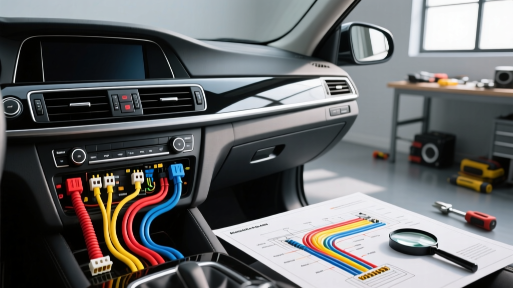
Decoding the Standard Alpine Head Unit Harness
When diagnosing electrical faults in an aftermarket car audio system, relying on guesswork leads to blown fuses, damaged head units, and frustrating hours of wasted labor. For Alpine head units, understanding the universal EIA/CEA color code standard is your first line of defense. While Alpine utilizes proprietary 18-pin or 22-pin connectors on the back of their chassis, the adapter harnesses (such as those from Metra or Axxess) translate these into the universal 16-pin aftermarket color code. Before grabbing a digital multimeter (DMM), you must understand the baseline specifications of these circuits.
According to the SAE J1128 Low Tension Primary Cable Standard, automotive wiring must handle specific thermal and voltage drop thresholds. The standard Alpine head unit harness utilizes 18 AWG stranded copper wire for power, ground, and speaker outputs, which is sufficient for the typical 10A draw of a modern digital media receiver. However, high-current draws require verifying the integrity of these color-coded paths.
Universal Alpine Color Code Reference Chart
| Wire Color | Function | AWG | Typical 16-Pin Location |
|---|---|---|---|
| Yellow | Constant 12V+ (Memory/Backup) | 18 AWG | Pin 9 |
| Red | Switched 12V+ (Ignition/Accessory) | 18 AWG | Pin 10 |
| Black | Chassis Ground | 18 AWG | Pin 11 |
| Blue / White Stripe | Amplifier Remote Turn-On | 18 AWG | Pin 5 |
| Orange / White Stripe | Illumination / Dimmer Signal | 18 AWG | Pin 6 |
| White / White-Black | Front Left Speaker (+ / -) | 18 AWG | Pins 13 / 14 |
| Gray / Gray-Black | Front Right Speaker (+ / -) | 18 AWG | Pins 15 / 16 |
| Green / Green-Black | Rear Left Speaker (+ / -) | 18 AWG | Pins 1 / 2 |
| Purple / Purple-Black | Rear Right Speaker (+ / -) | 18 AWG | Pins 3 / 4 |
Troubleshooting Flow 1: Head Unit Will Not Power On
Symptom: The Alpine unit display remains completely blank when the ignition is turned to the ACC or ON position. No illumination, no audio, no response to the reset button.
Primary Cause: Loss of switched 12V (Red), loss of constant 12V (Yellow), or a compromised ground path (Black).
Step-by-Step Diagnostic Actions
- Verify the Inline Fuse: Locate the inline ATC/ATO blade fuse holder on the Red or Yellow wire of the Alpine harness. Most Alpine units require a 10A fuse. If the fuse is blown, do not simply replace it; a blown fuse indicates a dead short to ground downstream. Inspect the wire routing for pinched harnesses behind the DIN sleeve.
- Test Constant 12V (Yellow Wire): Set your DMM to DC Voltage. Place the black probe on a known good chassis ground and the red probe on the Yellow wire of the vehicle-side harness. You should read between 12.2V and 12.6V with the key OFF. If you read 0V, trace the Yellow wire back to the battery or fuse box.
- Test Switched 12V (Red Wire): Keep the black probe on the chassis ground. Move the red probe to the vehicle-side Red wire. Turn the ignition to ACC. The DMM should now read 12.2V+. If the Yellow wire has power but the Red wire does not, the head unit will not boot, as Alpine logic gates require both circuits to initialize the microprocessor.
- Perform a Ground Voltage Drop Test: A common failure point is a poor ground connection to a painted dash support bracket. Turn the ignition ON. Place your DMM in DC Voltage mode. Put the red probe on the Black wire at the harness connection and the black probe on the bare metal chassis. A reading above 0.1V indicates excessive resistance. Scrape away paint, use a star washer, and secure the ground ring terminal directly to bare metal.
Troubleshooting Flow 2: Radio Loses Memory and Presets
Symptom: The Alpine stereo powers on and functions perfectly while driving, but every time you turn off the ignition, the clock resets to 12:00, and all radio presets and EQ settings are erased.
Primary Cause: The Constant 12V (Yellow) and Switched 12V (Red) circuits are reversed at the vehicle adapter harness. This is an extremely common issue in specific vehicle platforms, notably Volkswagen, Audi, Jeep, and some General Motors models, where the factory harness swaps the constant and switched power pins.
Step-by-Step Diagnostic Actions
- Confirm the Reversal: With the vehicle key completely OFF and removed from the ignition, use your DMM to test the vehicle-side adapter harness. Probe the wire that connects to the Alpine Yellow (Constant) wire. If it reads 0V, and the wire connecting to the Alpine Red (Switched) wire reads 12.4V, the circuits are reversed.
- Execute the Swap: Most high-quality wiring adapters (like those documented in the Crutchfield Car Stereo Installation Guide) feature inline bullet connectors specifically for the Red and Yellow wires to facilitate this exact swap. Disconnect the bullet connectors and cross-connect the Red and Yellow wires. If your harness was hard-soldered, you must cut the wires, swap them, and re-solder using adhesive-lined heat shrink tubing to prevent future oxidation.
- Verify Parasitic Draw: After swapping, ensure the vehicle-side constant 12V wire does not exceed 5mA of draw when the vehicle is asleep. Alpine head units typically draw 2mA to 4mA for memory retention. If the draw is higher, inspect the Orange/White illumination wire for a short to ground, which can keep the unit's backlighting circuit partially awake.
Troubleshooting Flow 3: No Audio Output or Blown Internal Amp
Symptom: The head unit powers on, the display functions, and source selection works, but there is zero audio output from the speakers, or the unit intermittently shuts off audio and displays an 'ERROR' or 'PROTECT' message.
Primary Cause: Speaker wire short to chassis ground, incorrect impedance load, or improper use of the remote turn-on wire.
Step-by-Step Diagnostic Actions
- The BTL Amplifier Warning: Modern Alpine head units utilize Bridge-Tied Load (BTL) internal amplifiers. This means BOTH the positive and negative speaker wires carry amplified voltage. Never ground the negative speaker wires (Black stripes) to the vehicle chassis. Doing so will instantly short the internal amplifier IC, triggering thermal protection or permanently destroying the output chip. If you suspect a ground short, disconnect the harness immediately.
- Test Speaker Continuity: Disconnect the head unit harness. Set your DMM to the Ohms (Ω) setting. Measure across the positive and negative wires for a single speaker channel (e.g., White and White/Black). A standard 4-ohm car speaker should read between 3.2Ω and 4.0Ω. If it reads 0Ω (dead short) or OL (open loop/infinite), you have a pinched speaker wire or a blown voice coil in the door panel.
- Check for Chassis Shorts: With the DMM still in Ohms, place one probe on the speaker negative wire (e.g., White/Black) and the other on the vehicle chassis ground. The meter should read OL (infinite resistance). If it reads continuity (near 0Ω), the speaker wire is pinched against bare metal somewhere in the door boot or kick panel. You must reroute and repair the wiring.
- Verify Amplifier Remote Turn-On: If you are bypassing the internal amp to run external amplifiers, ensure you are using the Blue/White wire, not the solid Blue wire. According to Alpine USA Official Manuals, the solid Blue wire is strictly for powering motorized antennas and may turn off when you switch to CD or AUX modes, causing your external amplifiers to shut off mid-listening. The Blue/White stripe wire provides a continuous 12V+ remote signal regardless of the source mode.
Advanced Diagnostics: Dealing with Alternator Whine
If your Alpine stereo powers on and plays audio, but you hear a high-pitched whining noise that rises and falls with the engine's RPM, you are experiencing a ground loop. This is rarely a fault of the head unit itself, but rather a discrepancy in ground potential between the head unit and external amplifiers.
To diagnose this using your color code diagram, focus on the Black ground wire. Ensure the head unit's ground wire is as short as possible (under 12 inches) and is bolted to a thick, unpainted structural steel point behind the dash. Do not daisy-chain the head unit ground with other accessories like radar detectors or backup cameras. If the whine persists, use a DC millivolt meter to measure the voltage difference between the head unit's Black wire ground point and the amplifier's ground point in the trunk. Any reading above 0.05V DC indicates a ground loop that must be resolved by relocating the amplifier ground or installing a ground loop isolator on the RCA interconnects.