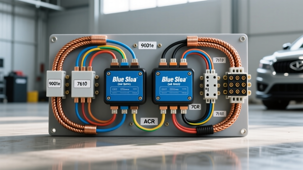
Architecture of the Blue Sea 9001e and 7610 ACR System
When engineering a dual-battery topology for overland, marine, or heavy-duty agricultural applications, relying on generic solid-state isolators leads to unacceptable voltage drop and parasitic drain. The gold standard for high-current DC power distribution is the combination of the Blue Sea Systems 9001e manual selector switch and the 7610 Automatic Charging Relay (ACR). This advanced technical deep dive dissects the exact blue sea dual battery switch wiring diagram, focusing on AWG sizing, torque specifications, and failure-mode mitigation.
The 9001e switch provides a 350A continuous and 600A intermittent rating, utilizing silver-plated copper contacts to minimize resistance. When paired with the 7610 ACR, the system automatically parallels the starting and house batteries when charging voltage is detected, and isolates them when the voltage drops, ensuring the cranking battery is never depleted by auxiliary loads like winches, fridges, or lighting arrays.
Component Specifications and AWG Requirements
Proper execution of this blue sea dual battery switch wiring diagram requires strict adherence to ampacity ratings and voltage drop limits. The following table outlines the core specifications for a standard 12V DC system with cable runs under 15 feet.
| Component | Model / Spec | Continuous Rating | Terminal / Stud Size | Required Wire Gauge |
|---|---|---|---|---|
| Manual Switch | Blue Sea 9001e | 350A | 3/8'-16 (x4) | 2/0 AWG |
| ACR (VSR) | Blue Sea 7610 | 120A | 3/8'-16 (x2), 1/4' (GND) | 4 AWG (Power), 10 AWG (GND) |
| Main Fusing | Class T Fuse | 300A | 5/16' or 3/8' | 2/0 AWG |
| Ground Cabling | SAE J1128 Compliant | 350A+ | Match Battery Post | 2/0 AWG |
Step-by-Step Wiring Diagram Execution
Stage 1: High-Current Battery and Switch Routing
The foundation of the blue sea dual battery switch wiring diagram relies on minimizing voltage drop across the primary high-current paths. According to SAE J1128 standards for low-tension primary cable, you must use pure copper, stranded wire. For runs up to 15 feet carrying up to 300A, 2/0 AWG is mandatory to keep voltage drop below 3% (0.36V on a 12V system).
- Battery 1 (Starting) to Switch: Route a 2/0 AWG red cable from the positive terminal of Battery 1 to Stud 1 on the Blue Sea 9001e switch.
- Battery 2 (House/Aux) to Switch: Route a 2/0 AWG red cable from the positive terminal of Battery 2 to Stud 2 on the 9001e switch.
- Switch Common to Loads: Connect a 2/0 AWG red cable from the 'C' (Common) stud on the switch to your main positive distribution busbar or directly to the starter solenoid.
- Grounding Topology: Connect both battery negative terminals to a common, heavy-duty chassis ground point using 2/0 AWG black cable. Do not rely on the engine block alone for the house battery ground; run a dedicated cable to the primary chassis ground busbar to prevent ground loops and alternator whine in audio systems.
Technical Note on Crimping: For 2/0 AWG lugs, use a hydraulic crimper with a hex die, not an indent die. Hex crimping provides uniform compression and maximum surface area contact, which is critical when sustaining high-draw loads like a 12,000lb winch. Always seal the crimp with dual-wall, adhesive-lined heat shrink to prevent capillary action from drawing moisture into the copper strands.
Stage 2: ACR (Voltage Sensitive Relay) Integration
The Blue Sea 7610 ACR manages the charging logic. It monitors voltage on both large studs and engages the internal solenoid to parallel the batteries when it detects a charging state (typically 13.0V for 30 seconds).
- ACR Stud A: Connect a 4 AWG red cable from ACR Stud A to the Battery 1 side of the circuit (either directly to the battery post or the switch's Stud 1).
- ACR Stud B: Connect a 4 AWG red cable from ACR Stud B to the Battery 2 side of the circuit.
- ACR Ground (Critical): The 7610 requires a dedicated ground to operate its internal logic board and solenoid coil. Use a 10 AWG black wire with a ring terminal on the 1/4' ground stud. Failure Mode Alert: Do not ground this to a random painted chassis bolt. The ACR ground must terminate directly at the battery negative terminal or a dedicated, cleaned copper busbar tied directly to the battery. A poor ground will cause the ACR's internal logic to read false voltages, resulting in rapid 'chattering' (opening and closing) which will destroy the solenoid contacts over time.
Stage 3: Circuit Protection and Fusing Topology
As detailed in the Blue Sea Systems Circuit Protection Guide, high-current battery cables must be fused within 7 inches of the battery positive terminal to protect against catastrophic short circuits. Standard ANL fuses are insufficient for modern high-CCA AGM or Lithium Iron Phosphate (LiFePO4) batteries due to their lower Ampere Interrupting Capacity (AIC).
You must use Class T fuses rated for 300A. Class T fuses offer an AIC of 20,000 Amps at 14V DC, ensuring the fuse will safely extinguish the arc even in a dead short scenario where a lithium battery can dump thousands of amps instantaneously. Install a Class T fuse block on the positive cable of Battery 1 and Battery 2 immediately adjacent to the battery posts.
Advanced Troubleshooting and Voltage Drop Analysis
Even with a flawless blue sea dual battery switch wiring diagram, environmental factors and vibration can introduce faults. Use a digital multimeter (DMM) to perform the following diagnostic checks:
Symptom: High Voltage Drop Across the 9001e Switch
Test: Set DMM to DC Volts. Place the red probe on the active input stud (e.g., Stud 1) and the black probe on the Common (C) stud while the vehicle is running and drawing a load (e.g., headlights and blower motor on).
Analysis: A healthy switch should exhibit a voltage drop of less than 0.05V at 100A. If the drop exceeds 0.10V, the internal contacts are pitted, or the terminal nuts are loose.
Fix: Verify torque on the 3/8' nuts. The specification is 120 in-lbs (10 Nm). Over-torquing can strip the brass studs; under-torquing creates micro-arcing and heat buildup. If torque is correct but voltage drop remains high, the switch must be replaced, as internal silver plating has degraded.
Symptom: ACR Chattering or Failure to Combine
Test: Monitor voltage at the ACR Stud A and Stud B relative to the ACR ground wire using a DMM.
Analysis: The 7610 ACR combines at 13.0V and opens at 12.35V. If the alternator is outputting 14.2V at the battery, but the ACR only reads 12.8V due to undersized 4 AWG sense wires or a corroded ground, the ACR will fail to combine. Conversely, if a heavy load (like a fridge compressor) kicks on and pulls the system voltage down to 12.4V momentarily, the ACR may open and immediately close, causing a loud, rapid clicking.
Fix: Upgrade the ACR power cables to 2 AWG if runs exceed 10 feet to minimize voltage drop. Ensure the 10 AWG ground wire is pristine. For severe voltage sag scenarios, integrate a Blue Sea 9012 ACR Control Switch or a time-delay relay to stabilize the combine threshold.
Authoritative References and Standards
Engineering a reliable DC power distribution network requires adherence to established electrical standards. The methodologies outlined in this blue sea dual battery switch wiring diagram guide are derived from the following authoritative resources:
- SAE J1128: Standard for Low Tension Primary Cable, defining the thermal and physical requirements for automotive copper wiring.
- Blue Sea Systems Technical Documentation: For comprehensive details on ACR logic states, coil draw, and solenoid lifecycle ratings, refer to the ACR Technical Document.
- ABYC E-11: While primarily a marine standard, the American Boat & Yacht Council's DC electrical guidelines are the benchmark for high-vibration, high-moisture overland and expedition vehicle builds, particularly regarding crimp sealing and fuse AIC ratings.
By strictly following these routing, crimping, and fusing protocols, your dual-battery system will deliver uncompromised cranking power while safely managing high-draw auxiliary accessories in the most demanding environments.