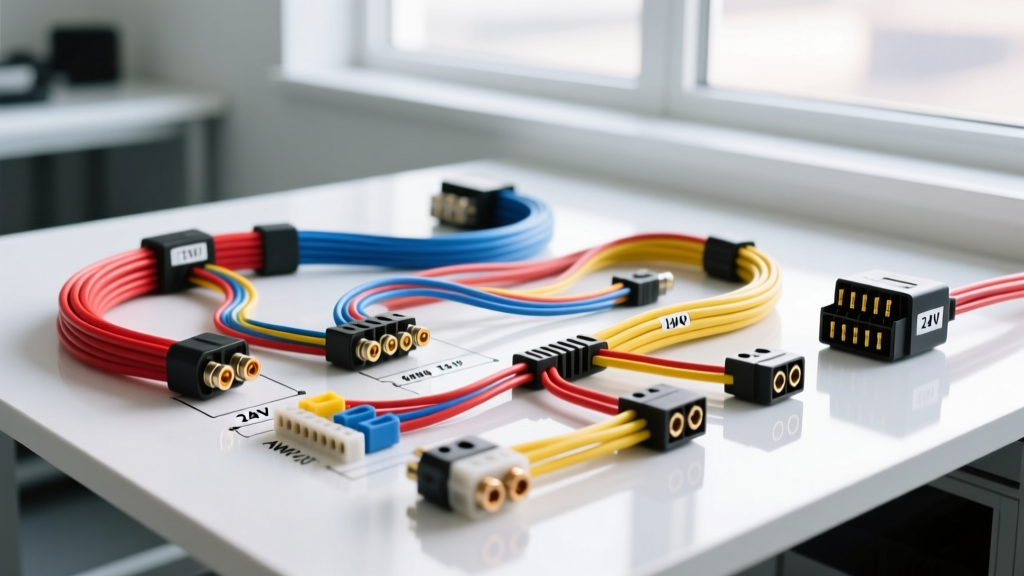
The Shift to Electric AC Compressors in Automotive Systems
The transition from belt-driven swashplate compressors to variable-speed electric scroll compressors represents one of the most significant architectural shifts in modern vehicle thermal management. When selecting an electric ac for car applications—whether for a classic car restomod, an EV conversion, an auxiliary sleeper cab, or a modern hybrid repair—the electrical demands and control topologies vary wildly. Unlike traditional compressors that parasitize engine horsepower via a magnetic clutch, electric compressors draw directly from the vehicle's electrical architecture, requiring precise wire gauge sizing, dedicated high-amperage fusing, and in OEM applications, complex LIN (Local Interconnect Network) bus integration.
At AutoFlowWire, we frequently see failed installations caused by treating an electric compressor like a simple 12V accessory. An electric AC compressor is a high-draw, continuous-load inductive device. This guide breaks down the voltage architectures, critical oil conductivity specifications, and exact wiring matrices required for a reliable installation.
Comparing Voltage Architectures: 12V vs. 24V vs. High-Voltage
The market for electric AC compressors is segmented by voltage, which directly dictates the amperage draw, wire gauge requirements, and safety protocols. Selecting the wrong architecture for your vehicle's electrical system will result in catastrophic voltage drop, melted harnesses, or immediate HV isolation faults.
| Compressor Type | Nominal Voltage | Peak Amperage | Typical BTU/hr | Primary Application | Required Oil Type |
|---|---|---|---|---|---|
| Universal DC (12V) | 12V - 14.4V DC | 45A - 65A | 8,000 - 12,000 | Restomods, EV Conversions, Aux Cabs | PAG 46 or POE |
| Heavy Duty DC (24V) | 24V - 28V DC | 25A - 35A | 14,000 - 18,000 | Semi-Trucks, Buses, Military | PAG 46 or POE |
| OEM High-Voltage (HV) | 300V - 400V DC | 3A - 8A | 15,000 - 22,000 | Factory EVs and Hybrids (e.g., Leaf, Bolt) | ND-OIL 11 (Low Conductivity) |
The Critical Danger of Oil Conductivity in HV Systems
One of the most heavily misunderstood aspects of electric AC for car systems is refrigerant oil selection. Standard belt-driven systems use PAG (Polyalkylene Glycol) oil. PAG oil is highly hygroscopic (absorbs moisture) and is electrically conductive. If PAG oil is introduced into a High-Voltage (300V+) electric compressor, the conductive oil will bridge the internal stator windings, causing a massive short circuit. The vehicle's Battery Management System (BMS) will instantly detect an isolation fault and disconnect the main high-voltage contactors, immobilizing the vehicle. OEM HV compressors strictly require low-conductivity POE (Polyolester) or specialized formulations like ND-OIL 11. Always verify the dielectric breakdown voltage of the oil before servicing an electric compressor.
12V Universal Compressor: Wiring Architecture & Circuit Integration
For 12V restomods and EV conversions utilizing universal DC compressors (such as those from RedDot or Vintage Air), the primary challenge is managing the massive continuous current draw. A compressor pulling 50A continuously will quickly overwhelm a stock 105A alternator, especially when electric cooling fans (20A) and fuel pumps (15A) are factored in. An alternator upgrade to a 160A+ high-output unit is typically mandatory.
Heavy-Gauge Power Delivery Matrix
Do not use standard automotive primary wire for the main power delivery. You must use stranded, oxygen-free copper (OFC) welding cable or SAE J1128 compliant SGX wire to handle the thermal load without voltage drop. The maximum acceptable voltage drop under full compressor load is 0.3V.
| Circuit Segment | Wire Gauge (AWG) | Connector Type | Protection / Fusing |
|---|---|---|---|
| Battery (+) to ISO Relay (Pin 30) | 2 AWG | 3/8" Ring Terminal, Heat Shrink | 70A MAXI Fuse (within 18" of battery) |
| ISO Relay (Pin 87) to Compressor (+) | 4 AWG | Sealed Weather-Pack or Deutsch DT | None (Protected by main MAXI) |
| Compressor (-) to Chassis Ground | 4 AWG | 3/8" Ring to Bare Metal (No paint) | N/A |
| Ignition Switch to Relay Coil (Pin 86) | 16 AWG | Standard Spade / Piggyback | 5A ATO Blade Fuse |
| Relay Coil (Pin 85) to Ground | 16 AWG | Ring Terminal | N/A |
Control Circuit & Standard ISO Relay Pinouts
Universal 12V compressors utilize a standard 4-pin or 5-pin ISO mini relay (per ISO 7588 standards) for switching. Never run the compressor's trigger wire directly through the dashboard HVAC switch; the 50A inductive kickback will melt the switch contacts instantly.
Pin 30: 12V Constant Battery Power (Heavy Gauge)
Pin 87: 12V Load Output to Compressor (Heavy Gauge)
Pin 86: 12V Trigger from HVAC Thermostat/Pressure Switch
Pin 85: Ground
Pro-Tip: Install a flyback diode across pins 85 and 86 (cathode to 86, anode to 85) to suppress the inductive voltage spike when the relay coil de-energizes, protecting sensitive ECU logic circuits in modern EV conversions.
High-Voltage (HV) OEM Compressor: LIN Bus & Shielded Routing
Modern factory EVs and hybrids do not use simple 12V relays. The HV compressor is integrated into the vehicle's CAN/LIN network, allowing the HVAC module to command variable compressor speeds (typically 1000 to 8000 RPM) based on cabin thermal load and battery cooling requirements.
LIN Bus Connector Pin Configuration
The control harness for an HV compressor typically features a 3-pin low-voltage connector alongside the massive 2-pin high-voltage power connector.
Pin 1 (12V IGN): Wake-up signal from the Body Control Module (BCM). Without this 12V reference, the compressor's internal inverter remains asleep.
Pin 2 (GND): Logic ground reference.
Pin 3 (LIN Signal): PWM data line. The HVAC module sends a duty-cycle command over this single wire to dictate scroll speed.
High-Voltage Cable Routing & SAE Standards
The main power cables feeding the HV compressor carry up to 400V DC. These cables must comply with SAE J1673 standards for EV wiring. They feature a distinctive bright orange jacket and an internal braided shield to prevent Electromagnetic Interference (EMI) from disrupting the LIN bus or nearby wheel speed sensors. When replacing these cables, the shield must be properly terminated to the compressor casing ground to maintain the Faraday cage effect. Crimping requires specialized hex-crimp HV terminals; standard copper lugs will create micro-arcing points that lead to thermal runaway.
Real-World Failure Modes & Troubleshooting Decision Tree
When an electric AC for car system fails, the root cause is almost always electrical rather than mechanical. Use this diagnostic matrix to isolate the fault:
- Symptom: Compressor relay clicks rapidly (chatter) but compressor does not spin.
Cause: Severe voltage drop on the ground path or undersized power wire. The inverter draws high startup current, voltage sags below the relay coil's holding threshold, relay opens, voltage recovers, relay closes (repeat).
Fix: Measure voltage drop across the ground cable under load. If >0.2V, sand the chassis ground point to bare metal and upgrade to 2 AWG wire. - Symptom: EV throws 'High Voltage Isolation Fault' and disables AC.
Cause: Dielectric breakdown inside the compressor. Caused by using conductive PAG oil instead of ND-OIL 11, or moisture contamination in the POE oil.
Fix: Isolate the compressor via the service disconnect. Megger test the compressor pins to the casing. If resistance is below 20 Megohms, the compressor is internally shorted and must be replaced. Flush the entire system and evacuate to 500 microns to remove moisture. - Symptom: Compressor receives 12V wake-up but ignores LIN bus commands.
Cause: Missing logic ground or corrupted LIN signal due to EMI from unshielded HV cables.
Fix: Verify Pin 2 continuity to chassis ground. Check Pin 3 with an oscilloscope; a healthy LIN signal shows a clean 12V square wave. If the wave is jagged, inspect the HV orange cable shielding for proper termination.
Conclusion
Upgrading or repairing an electric AC system requires a fundamental understanding of both thermal dynamics and high-current electrical architecture. Whether you are pulling 60 amps through a 4 AWG wire in a 12V restomod or routing shielded 400V lines in a modern EV, respecting wire gauge limits, oil dielectric properties, and relay logic is non-negotiable. For more detailed wiring schematics and pinout diagrams, consult the Bosch Mobility Solutions thermal management documentation or your vehicle's specific factory service manual.