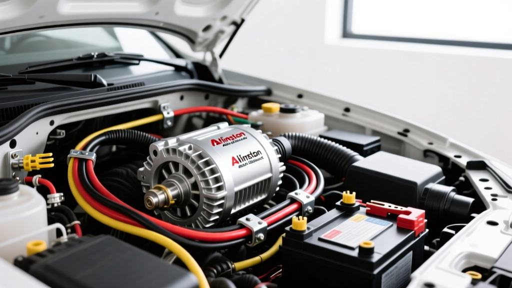
Why the Arlington Auto Electric Standard Matters for High-Amp Upgrades
When overlanders, off-road enthusiasts, and custom vehicle builders push electrical systems beyond factory limits, the margin for error vanishes. Adding a 250A high-output alternator, a dual-battery smart isolator, and high-draw accessories like electric winches or auxiliary lighting requires more than just thicker cables. It demands a systematic approach to voltage drop mitigation, thermal management, and circuit protection. Master technicians at renowned facilities like Arlington Auto Electric have long set the benchmark for these complex overland electrical overhauls. The 'Arlington Auto Electric standard' refers to a rigorous methodology of using marine-grade tinned copper, precision hex-crimping, and strategic 3-wire alternator sensing that eliminates the chronic charging failures seen in amateur builds.
Upgrading from a stock 100A-140A alternator to a 200A+ unit (such as those from MechMan or DC Power) introduces massive thermal loads and current spikes. If your main power cables, exciter circuits, and grounding points are not spec'd correctly, you will experience severe voltage drop, premature diode failure, and potential fire hazards. This guide breaks down the exact wiring protocols, AWG sizing, and pinout configurations required to execute a high-amp alternator and dual-battery upgrade to professional fleet standards.
Calculating Amperage Load and Selecting AWG Wire
The most common failure point in high-amp upgrades is undersized main output wiring. Many builders mistakenly use 4 AWG or 2 AWG wire for a 250A alternator, assuming that because it physically bolts to the terminal, it can handle the current. According to SAE J1128 standards for automotive primary wire, continuous current capacity drops significantly when wire is bundled or routed through high-temperature engine bays.
The Arlington Auto Electric methodology dictates a maximum voltage drop of 0.10V (100mV) across the main positive cable from the alternator B+ terminal to the primary battery positive post under full continuous load. To achieve this over a standard 6-to-8 foot run in an engine bay environment, you must use 1/0 AWG (one-aught) or 2/0 AWG marine-grade tinned copper wire. Tinned copper resists the black oxidation that plagues bare copper in under-hood environments, ensuring the crimp joint remains conductive for the life of the vehicle.
High-Amp Cable Sizing & Fusing Reference Chart
| Alternator Max Output | Recommended Wire Gauge | Max Run Length (Engine Bay) | Required ANL / Class-T Fuse | Terminal Lug Crimp Die |
|---|---|---|---|---|
| 150A - 180A | 2 AWG Tinned Copper | Up to 8 feet | 200A ANL | #2 AWG Hex |
| 190A - 220A | 1/0 AWG Tinned Copper | Up to 10 feet | 250A ANL | 1/0 AWG Hex |
| 230A - 270A | 2/0 AWG Tinned Copper | Up to 12 feet | 300A Class-T | 2/0 AWG Hex |
| 280A - 350A+ | 4/0 AWG Tinned Copper | Up to 14 feet | 400A Class-T | 4/0 AWG Hex |
3-Wire Alternator Pinout: Upgrading from 1-Wire
Many off-the-shelf high-output alternators are sold as '1-wire' or 'self-exciting' units. While easy to install, 1-wire setups require the engine to be revved to 1,500+ RPM to trigger the internal regulator, and they suffer from poor voltage sensing at the battery. The professional standard is to wire the alternator in a 3-wire configuration, utilizing the factory-style harness plug to provide precise battery sensing and ignition-switched excitation.
For popular GM-style CS130, CS144, and AD244 case upgrades, the 4-pin connector (Pigtail PT113 or equivalent) is the industry standard. Even though it is a 4-pin plug, only three circuits are typically active for a standard high-amp upgrade.
GM-Style 4-Pin Connector Breakdown (Pins L, I, S, P)
- Pin L (Lamp / Exciter): This is the turn-on signal for the internal voltage regulator. Connect this to an ignition-switched 12V source. Crucial Detail: You must wire a 56-ohm resistor in parallel or use a standard incandescent dashboard warning bulb circuit to provide initial resistance. Without this resistance, the regulator may fail to excite at idle, or the dash bulb will glow dimly due to voltage bleed.
- Pin S (Sense): The most critical wire for high-amp setups. This provides direct voltage feedback to the regulator. Route an 12 AWG or 10 AWG red wire directly from this pin to the positive battery post or the main distribution busbar. Never connect the Sense wire to the alternator B+ terminal; doing so defeats the purpose of remote sensing and will cause undercharging at the battery due to voltage drop in the main 1/0 AWG cable.
- Pin I (Ignition): Often used in older SI-style systems, but on modern CS/AD regulators, this can be tied to the same ignition-switched source as Pin L, or left unpopulated depending on the specific regulator chip (e.g., Transpo or VR-H2000 series).
- Pin P (Phase): Used for tachometer signals or stator feedback. Generally left unpopulated for standard 12V DC charging upgrades unless interfacing with a specific marine tachometer or external regulator.
Dual Battery Smart Isolator Integration
When adding a secondary deep-cycle battery for auxiliary loads (fridges, lighting, inverters), a smart battery isolator (SBI) like the Redarc SBI12 or National Luna is mandatory. Old-school diode isolators introduce a 0.7V drop, which is unacceptable for modern AGM or Lithium auxiliary banks.
Wiring the SBI requires heavy-duty cabling for the main battery links and precise trigger wiring. The main positive cables connecting Battery A to the SBI, and the SBI to Battery B, should be a minimum of 2 AWG for runs under 6 feet, utilizing 150A to 200A Mega fuses within 18 inches of each battery's positive terminal. The SBI ground must be tied directly to the chassis or engine block using a dedicated 4 AWG ground strap, not shared with auxiliary lighting grounds, to prevent ground-loop voltage fluctuations that can trick the SBI's voltage-sensing microcontroller into prematurely disconnecting the batteries.
Circuit Protection: ANL vs. Class-T Fuses
As you cross the 200A threshold, standard ANL fuses begin to reach their thermal limits and interrupt capacities. The Arlington Auto Electric standard transitions to Class-T fuses for alternators rated 250A and above. Class-T fuses offer a much higher Ampere Interrupting Capacity (AIC)—typically 20,000 amps at 125VDC—compared to the 6,000 AIC of standard ANL fuses. In the event of a dead short (e.g., a chafed 1/0 AWG main cable grounding to the alternator casing), a Class-T fuse will extinguish the DC arc safely, whereas an ANL fuse can sustain an arc, melt the fuse block, and ignite the wire loom.
Always mount the main alternator fuse within 7 to 18 inches of the battery positive terminal, not near the alternator. The goal of this fuse is to protect the main cable run in the event the cable shorts to the chassis before it reaches the battery.
Professional Crimping and Environmental Sealing
Hand-crimpers with indent dies are insufficient for 1/0 AWG and larger wire in high-vibration environments. The professional standard requires a heavy-duty hex-crimp tool (such as the Knipex 97 51 10 or a hydraulic 12-ton press). A hex crimp deforms the copper strands and the terminal barrel into a unified hexagonal shape, creating a cold-weld that eliminates air pockets where moisture could ingress.
Following the crimp, seal the joint using 3M dual-wall adhesive-lined heat shrink with a 3:1 shrink ratio. The inner layer of thermoplastic adhesive melts and flows into the wire strands, creating a waterproof barrier that prevents the 'green rot' (copper oxidation) that causes high-resistance connections. Finally, wrap the entire engine-bay run in nylon braided cable loom and secure it every 10-12 inches with stainless steel P-clips and rubber cushioning to prevent abrasion against aluminum brackets or steel firewall edges.