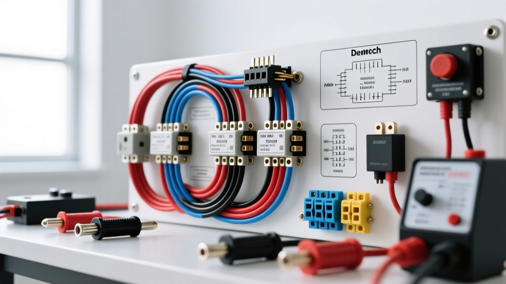
Why Build a Physical Rig for an Auto Electric Course?
When structuring a hands-on auto electric course, theoretical diagrams and multimeter exercises are not enough. Instructors and students require a reliable, modular 12V bench-top training rig to safely test circuits, simulate parasitic draws, and practice crimping without risking a donor vehicle's ECU or wiring harness. A properly designed training board bridges the gap between textbook theory and real-world automotive diagnostics.
This installation guide details the physical wiring of a modular 12V automotive training board. We will cover main power distribution, ISO mini relay integration, weather-sealed connector termination, and CAN bus simulation. By following these IPC/WHMA-A-620 wiring standards, you will build a rugged, fault-injectable rig suitable for advanced automotive electrical training.
Bill of Materials: Wiring and Hardware Specifications
Automotive environments demand specific wire insulation types. Standard PVC wire melts under hood temperatures and becomes brittle in cold weather. For this rig, we use cross-linked polyethylene (XLPE) wire to simulate real vehicle conditions.
| Component | Specification | AWG / Size | Color Code |
|---|---|---|---|
| Main Power Feed | SAE J1128 GXL Wire | 10 AWG | Red |
| Main Ground Return | SAE J1128 GXL Wire | 10 AWG | Black |
| Relay Control Circuits | SAE J1128 TXL Wire | 16 AWG | Yellow / Green |
| High-Current Loads (Starter Sim) | SGT Battery Cable | 4 AWG | Red / Black |
| CAN Bus Twisted Pair | Shielded Twisted Pair (STP) | 20 AWG | Green/White & Blue/White |
| Connectors | Deutsch DT Series (TE) | Size 16 Pins | N/A |
For comprehensive wire insulation standards, refer to the SAE J1128 Low Tension Primary Cable specification, which dictates the thermal and abrasion resistance required for automotive primary wire.
Phase 1: Main Power Distribution and Busbar Installation
Step 1: Sizing the Main Feed and Ground
The training rig will be powered by a 12V 30A DC switching power supply. To handle the continuous 30A load with a safety margin for transient spikes (such as relay coil inrush), we use 10 AWG GXL wire for the main feed. According to standard ampacity charts, 10 AWG GXL is rated for roughly 40A in a single-conductor, open-air bench environment.
- Overcurrent Protection: Install a 30A ANL fuse within 6 inches of the power supply positive terminal. Use a marine-grade ANL fuse block with tin-plated copper busbars to prevent galvanic corrosion.
- Busbar Mounting: Mount a 4-stud copper busbar (M6 thread) to the bench board. Torque the M6 stainless steel mounting nuts to 4.5 Nm (40 in-lbs) using a calibrated torque screwdriver. Apply a thin layer of dielectric grease (Noalox) to the terminal faces to prevent oxidation.
- Grounding: The 10 AWG black ground wire must terminate on a dedicated ground busbar. Ensure the resistance between the power supply negative terminal and the furthest ground stud on the board does not exceed 0.05 ohms.
Phase 2: Wiring the ISO Mini Relay Control Module
Relay logic is the backbone of any auto electric course. We will wire a standard Bosch-style ISO 7588-2 mini relay socket. This allows students to practice diagnosing fuel pump, headlight, and cooling fan circuits.
Standard Bosch 5-Pin Relay Pinout
| Pin Number | Function | Wire Color (Rig Standard) | Connection Destination |
|---|---|---|---|
| 30 | Common (Power In) | 10 AWG Red | Fused 12V+ Busbar |
| 87 | Normally Open (NO) | 14 AWG Blue | Load Component (e.g., Hella Headlamp) |
| 87a | Normally Closed (NC) | 14 AWG Brown | Secondary Load / Bypass Circuit |
| 85 | Coil Ground | 16 AWG Black | Ground Busbar or ECU Switch |
| 86 | Coil Power (Switch) | 16 AWG Yellow | Dashboard Switch / 12V+ Trigger |
Step 2: Installing Flyback Diodes
When students de-energize a relay coil, the collapsing magnetic field generates a high-voltage inductive kickback (often exceeding 100V). In a real vehicle, this spike can destroy solid-state transistor drivers inside an ECU. To teach proper circuit protection, solder a 1N4001 rectifier diode across pins 85 and 86 on the underside of the relay socket. The diode's cathode (silver stripe) must point toward Pin 86 (positive coil feed). This clamps the voltage spike to a safe ~0.7V.
Phase 3: Integrating Weather-Pack and Deutsch Connectors
Modern vehicles rely heavily on sealed connectors. Teaching students to properly crimp and extract pins is a mandatory module in any professional auto electric course. We will integrate TE Connectivity Deutsch DT series connectors into the training board's modular load banks.
Step 3: Proper Crimping and Wedgelock Insertion
- Wire Stripping: Strip 16 AWG TXL wire to exactly 3.5mm (0.138 inches). Do not nick the copper strands.
- Crimping: Use a calibrated Deutsch DT crimp tool (e.g., TE 1376352-1). Place the Size 16 pin (Part # 0460-202-1631) into the tool. The wire insulation crimp must grip the jacket tightly, while the wire crimp forms a symmetrical 'B' or 'F' shape. A proper crimp will exhibit a visible 'bellmouth' at the front of the wire barrel.
- Seal Insertion: Slide the green silicone wire seal over the wire before crimping. The seal must sit flush against the insulation crimp barrel.
- Housing and Wedgelock: Push the crimped pin into the DT06-2S plug housing until it clicks. Insert the orange plastic wedgelock (secondary retention) to lock the pin in place. Pull-test the wire with 15 lbs of force to verify retention.
Phase 4: CAN Bus Termination and OBD-II Breakout
To simulate modern networked vehicle architecture, the training rig includes an OBD-II J1962 breakout connector and a simulated CAN bus loop. This allows students to use oscilloscopes and scan tools to read network traffic.
- OBD-II Pin 6 (CAN-High): Wire to the CAN-H bus using 20 AWG Green/White wire.
- OBD-II Pin 14 (CAN-Low): Wire to the CAN-L bus using 20 AWG Blue/White wire.
- Twisted Pair Routing: The CAN-H and CAN-L wires must be twisted together at a rate of 1 twist per inch to reject electromagnetic interference (EMI).
- Termination Resistors: Install a 120-ohm, 1/4W carbon film resistor across the CAN-H and CAN-L lines at both physical ends of the training board's bus loop. Measuring between Pin 6 and Pin 14 at the OBD-II port with a multimeter should yield exactly 60 ohms (two 120-ohm resistors in parallel).
Troubleshooting Common Training Rig Faults
Instructors can intentionally introduce the following faults into the bench rig to test student diagnostic skills. Use this decision tree to guide the auto electric course troubleshooting module.
| Simulated Fault | Symptom on Rig | Diagnostic Procedure & Expected Finding |
|---|---|---|
| High Resistance Ground | Headlamp glows dimly; relay clicks weakly. | Perform voltage drop test across ground circuit. Expected: >0.5V drop across the intentionally corroded ground stud. |
| Blown Flyback Diode | ECU simulator resets when relay disengages. | Scope Pin 85/86. Expected: Inductive spike exceeding 40V upon coil de-energization (diode removed or installed backward). |
| CAN Bus Short to Ground | Scan tool shows U-code; no module communication. | Measure resistance from Pin 14 to Chassis Ground. Expected: <10 ohms (jumper wire intentionally installed). |
| Missing Wedgelock | Intermittent operation when harness is wiggled. | Visual inspection of Deutsch connector. Pin backing out due to missing secondary retention lock. |
Conclusion
Building a physical 12V bench rig transforms an auto electric course from a passive lecture into an active, diagnostic bootcamp. By adhering to SAE wire standards, implementing proper relay flyback protection, and enforcing strict Deutsch connector crimping protocols, you provide students with a realistic, fault-tolerant environment. This hands-on installation ensures that when students transition to live vehicles, they possess the muscle memory and diagnostic logic required to tackle complex automotive electrical gremlins safely and efficiently.