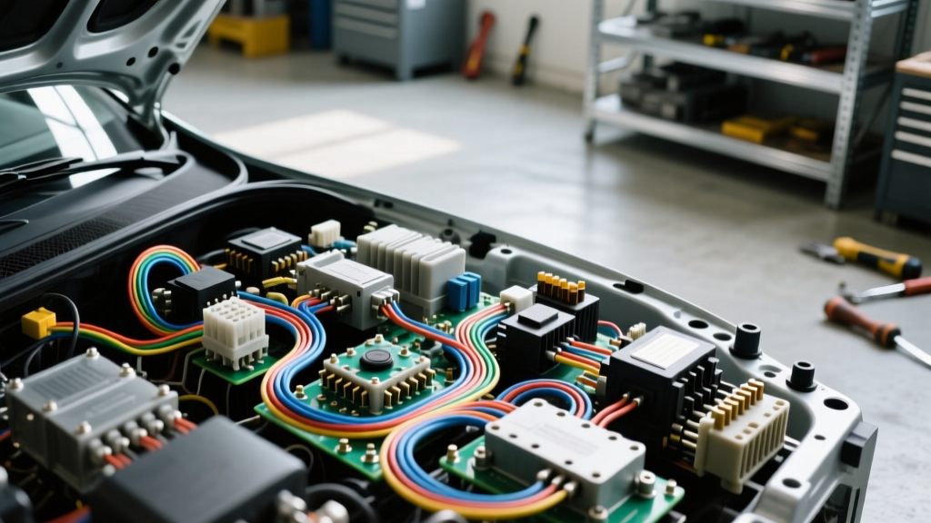
The Hidden Dangers of Inadequate Auto Electrical Training
While formal auto electrical training provides the foundational theory of Ohm's Law, Kirchhoff's circuit laws, and schematic reading, real-world application requires a strict adherence to safety protocols and an intimate understanding of common failure points. Modern vehicles are essentially rolling data centers, utilizing multiplexed networks, solid-state switching, and sensitive control modules. A single wiring mistake—such as using the wrong American Wire Gauge (AWG), improperly backprobing a sealed connector, or ignoring flyback voltage—can result in catastrophic harness fires, airbag deployment, or the destruction of a $2,500 Powertrain Control Module (PCM).
This guide highlights the most critical wiring mistakes and safety warnings that technicians and advanced DIYers encounter, bridging the gap between classroom theory and the harsh realities of the service bay.
Mistake #1: The "Upsized Fuse" Fallacy and AWG Mismatches
One of the most dangerous habits developed without proper auto electrical training is replacing a repeatedly blown fuse with one of a higher amperage rating. If a 15A MINI fuse protecting a fuel pump circuit blows, the correct diagnostic step is to locate the short to ground or the failing component. Upsizing to a 20A or 25A fuse bypasses the engineered safety limit of the wire.
Automotive primary cable, typically insulated with cross-linked polyethylene (TXL, GXL, or SXL per SAE J1128 standards), is rated for specific thermal limits. When current exceeds the wire's capacity, the copper core heats up, melting the insulation and potentially igniting surrounding materials long before the oversized fuse blows.
SAE Wire Gauge to Fuse Matching Specification Chart
| Wire Gauge (AWG) | Insulation Type | Max Continuous Ampacity | Recommended Max Fuse Size | Typical Application |
|---|---|---|---|---|
| 18 AWG | TXL / GXL | 6 Amps | 5A - 7.5A | Sensors, PCM logic triggers, interior LEDs |
| 16 AWG | TXL / GXL | 10 Amps | 10A | Radio memory, horn relays, tail lights |
| 14 AWG | TXL / GXL | 15 Amps | 15A | Fuel injectors, blower motor low speeds |
| 12 AWG | TXL / GXL | 20 Amps | 20A | Power windows, ABS valve solenoids |
| 10 AWG | TXL / SXL | 30 Amps | 30A | Fuel pump feeds, radiator fan low speed |
| 8 AWG | SXL | 40 Amps | 40A | Main power feeds, high-current amplifiers |
Note: Ampacity ratings assume a single conductor in free air at an ambient temperature of 125°C. Bundled harnesses require derating.
Mistake #2: Grounding Fallacies and Voltage Drop Ignorance
A circuit is only as good as its return path. A common mistake is assuming that any metal-to-metal contact on the chassis constitutes a valid ground. Modern unibody vehicles utilize extensive amounts of seam sealer, anti-corrosion coatings, and high-strength steel that can act as insulators. Furthermore, "daisy-chaining" multiple high-current grounds to a single M6 or M8 chassis stud creates a bottleneck, leading to voltage drop and module cross-talk.
Proper Grounding Protocol
- Surface Preparation: Always strip paint and clear coat down to bare, shiny metal using a brass wire brush or sanding disc. Apply a small dab of dielectric grease after securing the connection to prevent oxidation, but never between the mating surfaces.
- Terminal Selection: Use non-insulated, brazed-seam ring terminals. Avoid soldering ground wires; solder wicks into the wire strands, creating a rigid point that will inevitably snap under automotive vibration.
- Hardware & Torque: Use OEM-style serrated flange nuts or star washers to bite into the chassis. Torque M6 ground bolts to 10 Nm (89 lb-in) and M8 bolts to 20 Nm (15 lb-ft) to ensure consistent clamping force without stripping the blind nuts.
Performing a Voltage Drop Test
According to ASE testing standards, a acceptable voltage drop on a ground circuit should not exceed 0.10V (100mV) under load. To test:
- Set your Digital Multimeter (DMM) to DC Volts.
- Connect the red probe to the battery negative post (not the clamp).
- Connect the black probe to the component's ground terminal or mounting bracket.
- Activate the circuit. A reading of 0.45V indicates high resistance, meaning the PCM or component is being starved of its necessary return path, often resulting in erratic sensor readings or dim lighting.
Mistake #3: CAN Bus Destruction and Improper Backprobing
The Controller Area Network (CAN) bus is the central nervous system of modern vehicles. The high-speed CAN network (CAN-C) operates at 500 kbps, utilizing twisted pair wiring to reject electromagnetic interference (EMI). The most egregious mistake made by those lacking advanced auto electrical training is probing CAN lines with incandescent test lights or standard steel paperclips.
CAN Bus Pinout and Diagnostic Rules
At the standard OBD-II Data Link Connector (DLC), the CAN bus pins are strictly defined:
- Pin 6: CAN-High (Typically Yellow or White wire)
- Pin 14: CAN-Low (Typically Green or Purple wire)
- Pins 4 & 5: Chassis and Signal Grounds
CRITICAL WARNING: Never pierce CAN bus wires with a "T-pin" or splice into them. Piercing the insulation exposes the copper to moisture, leading to "green death" (copper oxidation) that alters the twisted pair's capacitance and causes network-wide communication faults (U-codes). Always use proper breakout boxes or designated diagnostic access ports.
Furthermore, the CAN network relies on two 120-ohm terminating resistors (usually located in the PCM and the instrument cluster) wired in parallel to create a 60-ohm impedance. If you measure the resistance between Pin 6 and Pin 14 with the battery disconnected and read 120 ohms, you have an open circuit in one of the terminating modules. If you read 0 ohms, the CAN-H and CAN-L wires are shorted together.
Mistake #4: Ignoring Relay Flyback Voltage
When an inductive load like a relay coil (Pins 85 and 86) is de-energized, the collapsing magnetic field induces a massive reverse-voltage spike—often exceeding 100 volts. If the relay is being switched by a PCM driver transistor or an aftermarket solid-state timer, this spike will instantly punch through the semiconductor junction, destroying the control module.
The Fix: Always install a flyback suppression diode across the relay coil. Wire the cathode (stripe) to the 12V+ side (Pin 86) and the anode to the switched ground side (Pin 85). This provides a safe recirculation path for the inductive spike. Many modern automotive ISO mini-relays come with this diode or a suppression resistor built-in; always verify the relay schematic printed on the casing before installing it in a sensitive solid-state circuit.
Safety Warnings: SRS and High-Voltage Protocols
Beyond component protection, personal safety is paramount. Automotive electrical systems contain hidden hazards that require strict procedural compliance.
Supplemental Restraint System (SRS) Safety
Airbag modules and pretensioners are triggered by squibs—small pyrotechnic heating elements. The wiring for these systems is universally wrapped in yellow loom and utilizes specialized shorting-bar connectors that short the deployment pins together when unplugged to prevent static discharge.
- Disconnect Procedure: Always disconnect the negative battery terminal and isolate it before working near yellow harnesses.
- Capacitor Discharge Wait Time: The SRS Diagnostic Trouble Code (DTC) module contains backup capacitors designed to deploy airbags even if the main battery is destroyed in a crash. You must wait a minimum of 15 minutes (consult OEM service data, as some manufacturers require up to 30 minutes) after battery disconnect before touching any yellow connectors.
- Multimeter Warning: Never use a standard DMM to measure the resistance of an airbag squib. The milliamps output by the meter's internal battery during a resistance test can be enough to initiate the pyrotechnic charge.
Multimeter Category Ratings
When working on modern 48V mild-hybrid systems or diagnosing alternator output spikes, ensure your DMM is rated for at least CAT III 600V. Using a cheap, unrated multimeter on an automotive circuit can result in an arc flash inside the meter if a transient voltage spike (like a load dump from a failing alternator diode bridge) bridges the internal gaps, potentially causing severe burns or blindness.
Conclusion
True proficiency in automotive wiring goes far beyond splicing two wires together with a crimp connector. It requires a deep respect for thermal limits, network topology, and the volatile nature of inductive circuits. By adhering to SAE wire specifications, utilizing proper voltage drop diagnostics, and respecting the safety boundaries of CAN and SRS systems, you ensure both the longevity of the vehicle's electrical architecture and your own personal safety. Continuous, hands-on auto electrical training and consultation of OEM wiring diagrams via resources like MOTOR Information Systems remain the best defenses against costly and dangerous mistakes.