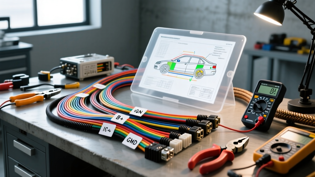
Establishing the Hans Auto Electric Benchmark in Modern Diagnostics
In the realm of advanced automotive electrical systems, the 'Hans Auto Electric' methodology has become an industry shorthand for rigorous, no-nonsense diagnostic procedures. Originally rooted in specialized European and German vehicle electrical architecture, this approach rejects guesswork and parts-cannon troubleshooting in favor of empirical data, oscilloscope waveform analysis, and precise voltage-drop testing. For shop owners and advanced DIYers looking to replicate this level of diagnostic certainty, understanding the tool requirements, capital expenditure, and consumable costs is critical.
Modern vehicle networks rely on high-speed CAN-bus (Controller Area Network) topology, LIN-bus sub-networks, and complex power management modules. A standard digital multimeter (DMM) is no longer sufficient to capture microsecond voltage spikes or module wake-up faults. This guide breaks down the exact tooling, cost analysis, and procedural standards required to perform auto electrical diagnostics at the Hans Auto Electric level.
Core Diagnostic Tooling Requirements & Cost Breakdown
To accurately diagnose parasitic draws, CAN-bus physical layer faults, and sensor signal degradation, a specific suite of professional-grade equipment is mandatory. Below is the capital expenditure analysis for setting up a diagnostic bench capable of meeting these rigorous standards.
| Equipment Category | Specific Tool / Model | Primary Application | Est. Cost (USD) |
|---|---|---|---|
| Automotive Oscilloscope | PicoScope 4425A (4-Channel) | CAN-bus decoding, sensor waveform capture, injector profiling | $1,350 |
| Industrial Multimeter | Fluke 87V with AutoHOLD | Millivolt drop testing, precise resistance, continuity | $480 |
| Current Clamp | Pico TA018 (60A/600A) | Starter motor profiling, alternator ripple, parasitic draw | $275 |
| Network Breakout Box | OBD-II CAN Breakout with Switches | Isolating CAN-H/CAN-L nodes, measuring termination resistance | $140 |
| Thermal Imaging | FLIR C5 or Seek Thermal | Fuse box hot-spot identification, shorted module detection | $550 |
| Wire Crimping System | Daniels M22520/2-01 Indent Crimper | MIL-SPEC and OEM Deutsch/MCON terminal crimping | $385 |
Total Initial Capital Investment: ~$3,180. While steep for a hobbyist, this tooling eliminates the cost of misdiagnosis, which frequently exceeds $1,500 in wasted OEM modules and labor hours on complex electrical faults.
The Hans Methodology: Non-Intrusive Parasitic Draw Testing
Traditional parasitic draw testing involves pulling fuses one by one while monitoring an ammeter in series with the battery. The Hans Auto Electric standard strictly forbids this practice on modern vehicles. Pulling a fuse drops network voltage to zero, forcing modules into a hard reset and waking up the CAN-bus, which masks the actual sleep-state current draw.
Procedure: Millivolt Fuse Drop Testing
Instead of breaking the circuit, professionals measure the voltage drop across the fuse while the vehicle is fully asleep (typically 20-40 minutes after key-off, depending on the OEM sleep cycle).
- Verify Sleep State: Connect a PicoScope to the OBD-II port Pin 6 (CAN-H) and Pin 14 (CAN-L). Confirm that network traffic has ceased and modules have transitioned to sleep (current draw should stabilize below 50mA).
- Measure Fuse Resistance: Using a Fluke 87V on the millivolt (mV) scale, place the probes on the exposed test points on the top of the mini/ATO fuses in the BCM (Body Control Module) fuse block.
- Apply Ohm's Law: A standard 10A mini-fuse typically exhibits a resistance of roughly 7.5 milliohms (0.0075 Ω). If you measure a voltage drop of 1.5mV (0.0015V) across the fuse, the current flow is calculated as: I = V / R (0.0015 / 0.0075 = 0.2A or 200mA).
- Isolate the Fault: A 200mA draw on a BCM circuit after the sleep cycle indicates a faulty interior lighting switch, a stuck relay, or a water-intruded LIN-bus slave module.
For deeper technical reference on network sleep states and current profiling, consult the Pico Technology Automotive Waveform Library, which provides benchmark captures for OEM-specific module sleep sequences.
CAN-Bus Physical Layer Topology & Breakout Analysis
When diagnosing U-codes (Network Communication DTCs), the Hans Auto Electric approach requires verifying the physical layer before condemning a module. High-speed CAN-bus operates as a differential signal pair.
Standard OBD-II CAN Pinout & Voltage Specifications
- Pin 6 (CAN-High): Recessive state ~2.5V | Dominant state ~3.5V. Typical wire color: Green or White/Green.
- Pin 14 (CAN-Low): Recessive state ~2.5V | Dominant state ~1.5V. Typical wire color: Blue or White/Blue.
- Termination Resistance: Measured with the battery disconnected between Pin 6 and Pin 14. Must read exactly 60 Ω (two 120 Ω resistors in parallel at the ends of the CAN backbone).
Common Failure Mode: If your Fluke 87V reads 120 Ω, one of the terminating modules (often the Engine Control Module or the Instrument Cluster) has been disconnected or has an internal open circuit. If you read 0 Ω, the CAN-H and CAN-L wires have shorted together, often due to chafing in the door jamb boot or under the driver's seat where harnesses pass through the floor pan.
For comprehensive network topology standards and wiring architecture, refer to the SAE J1939 and J2284 standards documentation, which governs high-speed CAN physical layer requirements.
Consumables and Harness Repair Cost Analysis
Proper electrical repair requires abandoning solder and electrical tape. Solder creates a rigid stress point that fractures under automotive vibration, and standard vinyl tape unravels in engine bay heat. The Hans standard mandates OEM-equivalent harness restoration materials.
| Material | Specification / Part Number | Use Case | Cost per Unit/Roll |
|---|---|---|---|
| TXL / GXL Wire | 14 AWG to 20 AWG (Cross-linked) | High-temp, thin-wall harness repair | $0.45 / ft |
| Fleece Tape | Tesa 51036 (19mm) | Interior harness wrapping (prevents dash rattles) | $18.00 / roll |
| Heat Shrink Tubing | 3M EPS300 (Adhesive-lined) | Waterproof sealing for splice joints (3:1 shrink ratio) | $2.50 / pc |
| Connectors | Deutsch DT Series / TE MCON | Engine bay and transmission sensor pigtails | $3.50 / set |
| Terminal Seals | Silicone Rubber Plugs (Green/Red) | Weatherproofing Deutsch/MCON crimps | $0.10 / pc |
The Importance of Proper Crimping and Torque Specs
Using the Daniels M22520 indenter crimper ensures the wire strands are compressed into the terminal barrel with the exact OEM pull-force rating. A proper crimp on a 16 AWG TXL wire to a Deutsch terminal should withstand a minimum pull force of 50 lbs before failure. Furthermore, when reattaching battery cables or main ground studs, torque specifications are paramount. For example, GM side-post battery terminal bolts require exactly 11 Nm (97 lb-in) of torque; over-torquing strips the internal lead threads, causing high-resistance voltage drops that mimic failing alternators or bad starter solenoids. For more on proper electrical termination and torque standards, review the Fluke Automotive Electrical Testing Guidelines.
ROI and Shop vs. DIY Considerations
Adopting the Hans Auto Electric tooling and methodology represents a significant upfront cost. However, the ability to accurately diagnose a CAN-bus short in 30 minutes using a PicoScope and breakout box, rather than spending 6 hours swapping modules, yields an immediate return on investment. For the advanced DIYer, investing in a high-quality DMM like the Fluke 87V and mastering millivolt drop testing will solve 90% of parasitic draw and ground-fault issues without ever needing to pierce a wire or back-probe a fragile connector.