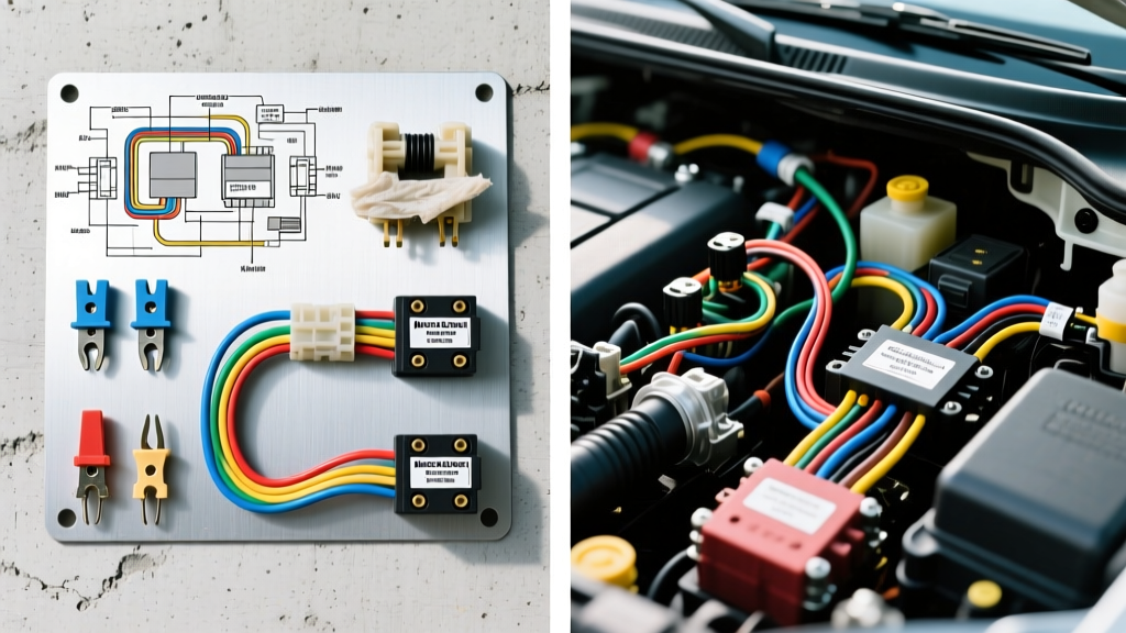
The True Cost of Professional Auto Electrical Diagnostics
Modern vehicle electrical architecture has evolved far beyond simple 12-volt DC circuits and mechanical relays. Today's CAN bus networks, multiplexed body control modules (BCMs), and variable-displacement alternators require a sophisticated approach to diagnostics. When enthusiasts face complex parasitic draws or communication faults, they often weigh the cost of a DIY repair against taking the vehicle to a professional specialist. If you have ever searched for a reliable moores auto electric service or similar high-end auto electrical shop, you have likely encountered diagnostic fees ranging from $150 to $225 per hour.
But what exactly are you paying for? Benchmarking against the rigorous standards of professional auto electricians, this analysis breaks down the true cost, tool requirements, and material investments necessary to perform OEM-level electrical diagnostics and wiring repairs at home. We will examine specific AWG ratings, pin configurations, and diagnostic methodologies to help you decide whether to build your own professional-grade toolkit or hand the keys to the experts.
Essential Tooling: DIY Baseline vs. Professional Standards
A standard $30 digital multimeter (DMM) from a hardware store is sufficient for checking battery voltage or basic continuity, but it is dangerously inadequate for modern vehicle networks. Professional shops rely on equipment that can capture microsecond anomalies and decode high-speed data buses.
Tier 1: The Advanced DIY Baseline ($600 - $900)
To safely troubleshoot starter circuits, alternator outputs, and basic sensor grounds, you must upgrade to an automotive-specific DMM and a circuit tester with built-in short protection.
- Fluke 88V Automotive Multimeter (~$450): Unlike standard DMMs, the Fluke 88V features a high-resolution duty cycle measurement, RPM inductive pickup, and a specialized low-impedance (LoZ) mode to eliminate ghost voltages on multiplexed circuits.
- Power Probe III (~$250): This tool allows you to safely apply 12V power or ground to a component (like a cooling fan relay or fuel injector) without risking damage to the PCM. If the circuit shorts, the internal breaker trips instantly, preventing harness fires.
Tier 2: The Professional Auto Electrician Standard ($2,500+)
Shops operating at the level of a top-tier moores auto electric facility invest heavily in oscilloscopes and breakout boxes to diagnose intermittent network faults and internal module failures.
- PicoScope 4225A Automotive Oscilloscope (~$1,600): Essential for viewing alternator ripple voltage (diode failures), decoding CAN High/CAN Low waveforms, and analyzing piezoelectric fuel injector current ramps.
- Fluke i410 AC/DC Current Clamp (~$350): Required for non-intrusive parasitic draw testing without waking up sleeping vehicle modules by breaking the circuit.
- OEM Breakout Boxes (~$400+): Used to back-probe PCM connectors safely without piercing wire insulation, which introduces moisture and future corrosion points.
Diagnostic Methodology: The Voltage Drop Parasitic Draw Test
One of the most common reasons DIYers fail at electrical diagnostics is improper parasitic draw testing. The outdated method of pulling fuses while watching an ammeter in series with the battery often wakes up the vehicle's BCM, resetting the sleep timer and leading to false conclusions.
Professional auto electricians use the mV Voltage Drop Method across the fuse box. According to SAE J1128 and OEM diagnostic trees, every blade fuse acts as a very low-value shunt resistor. By measuring the millivolt (mV) drop across the top test points of a fuse while the vehicle is asleep, you can calculate the exact current draw without breaking the circuit.
Fuse mV to Amps Conversion Chart (Standard ATO/ATC Fuses)
| Fuse Rating | mV Drop per 1 Amp | Acceptable Sleep Draw (mV) | Excessive Draw Indicator |
|---|---|---|---|
| 5 Amp (Tan) | ~1.80 mV / A | < 0.09 mV (50mA) | > 0.18 mV (100mA+) |
| 10 Amp (Red) | ~0.90 mV / A | < 0.045 mV (50mA) | > 0.09 mV (100mA+) |
| 15 Amp (Blue) | ~0.60 mV / A | < 0.03 mV (50mA) | > 0.06 mV (100mA+) |
| 20 Amp (Yellow) | ~0.45 mV / A | < 0.022 mV (50mA) | > 0.045 mV (100mA+) |
Note: Always refer to the specific manufacturer's mV chart printed on the fuse box lid or in the service manual, as metallurgical compositions vary between Littelfuse, Bussmann, and PAC fuses.
Material Costs: Wiring, Terminals, and Consumables
Beyond diagnostic tools, the cost of professional-grade consumables is a major factor. Hardware store wire and electrical tape are unacceptable for automotive environments due to under-hood temperatures, vibration, and chemical exposure.
Wire Gauge and Insulation Specifications
When performing high-current upgrades, such as installing a 200A Denso alternator or an electric AC compressor clutch conversion, wire sizing is critical. Standard PVC-insulated wire melts and degrades. Professionals use Cross-Linked Polyethylene (XLPE) insulated wire, rated for 125°C to 150°C.
- 1/0 AWG (53.5 mm²): Required for 200A+ alternator main output runs exceeding 4 feet. Must be terminated with 3/8-inch closed-end ring terminals and sealed with 3:1 adhesive-lined polyolefin heat shrink.
- 8 AWG (8.37 mm²): Ideal for electric cooling fan relays and high-amperage inverter feeds for hybrid/EV auxiliary systems.
- 14 AWG (2.08 mm²): Standard for 15A lighting circuits and accessory feeds.
Connector Architecture: Deutsch vs. Weather-Pack
Professional shops avoid cheap, stamped-brass connectors. For high-vibration and high-moisture environments (like engine bay sensors or transmission solenoids), the industry standard is the TE Connectivity AMP Superseal or the Deutsch DT series. A professional Deutsch DT crimping tool (capable of achieving the precise 4-indent quad-crimp on solid nickel-plated barrel pins) costs upwards of $250. Improper crimping leads to increased resistance, which causes voltage drop and eventual thermal failure of the connector housing.
Network Topology: CAN Bus and Terminating Resistors
Modern diagnostics heavily involve the Controller Area Network (CAN). If a DIYer is troubleshooting a 'U-code' (Network Communication Fault), they must understand the physical layer of the OBD-II port.
- Pin 6: CAN High (Typically 2.5V to 3.5V)
- Pin 14: CAN Low (Typically 1.5V to 2.5V)
The network relies on two 120-ohm terminating resistors located at the extreme ends of the bus (usually inside the PCM and the Instrument Cluster). When diagnosing a total network shutdown, a professional will measure resistance between Pin 6 and Pin 14 with the battery disconnected. A healthy network will read exactly 60 ohms (the parallel equivalent of two 120-ohm resistors). If the DMM reads 120 ohms, one module is missing or a wire is broken. If it reads near 0 ohms, the CAN bus is shorted to itself. Understanding this topology saves hours of needless module replacement.
Software and Information Systems: The Hidden Overhead
Tools and wire are only half the equation. You cannot accurately diagnose a multiplexed circuit without OEM wiring diagrams. Professional shops pay for subscriptions to ALLDATA, Mitchell 1, or Identifix, which cost between $150 and $350 per month per bay. These platforms provide the exact pinout charts, ground distribution locations (e.g., G204 behind the left kick panel), and splice pack identifiers necessary to trace a fault. A DIYer relying on free, user-uploaded forum diagrams risks chasing phantom circuits that were only present in early production runs or specific trim levels.
Decision Tree: When to DIY vs. When to Call the Professionals
Use this structured guide to determine if your current toolset and budget can handle the repair, or if it is time to seek out professional auto electrical services.
Scenario A: Accessory Installation (LED Light Bars, Winches, Audio)
- Requirement: Basic circuit calculation, proper AWG selection, relay wiring.
- Tooling Needed: Wire strippers, heat shrink, Fluke DMM, Power Probe.
- Verdict: DIY Friendly. The ROI on buying a Power Probe and quality crimpers is easily justified over a few custom accessory installs.
Scenario B: Intermittent Parasitic Draw or BCM Failure
- Requirement: Oscilloscope, current clamps, OEM wiring diagrams, module programming software.
- Tooling Needed: PicoScope, Identifix subscription, J2534 Pass-Thru programmer.
- Verdict: Professional Shop Recommended. The $3,000+ investment in advanced diagnostic software and oscilloscopes is rarely justifiable for a single vehicle owner. Paying a specialist for 2-3 hours of diagnostic time is vastly more cost-effective.
Scenario C: Alternator Ripple and Stator Diode Testing
- Requirement: AC voltage measurement at the battery terminals under load.
- Tooling Needed: Fluke 88V (AC mV setting) or Oscilloscope.
- Verdict: Borderline. If you already own a high-end automotive DMM, you can perform a ripple test (looking for < 50mV AC at 2000 RPM). If the AC voltage exceeds 100mV, the internal rectifier diodes are failing, and the alternator requires replacement.
Conclusion
The gap between a DIY enthusiast and a professional auto electrician is defined by diagnostic methodology, specialized tooling, and access to OEM data. While basic wiring repairs, alternator swaps, and accessory installations are well within the reach of a dedicated home mechanic equipped with a $600 toolset, network-level diagnostics and intermittent module faults require the heavy capital investment that only a dedicated shop can justify. By understanding the exact AWG requirements, pin configurations, and testing procedures outlined above, you can make an informed, cost-effective decision on how to tackle your vehicle's next electrical anomaly.